3 SETUP AND USE
g
GE Power Management
30
No. Name Description
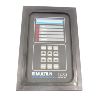
17 SERVICE LED indicator used to show the result of the 169 self-test feature. When flashing, the relay
has failed the self-test and service is required. When on steady, the supply voltage may be
too low. This LED may be on momentarily during relay power up.
3.2 169 Relay Display Modes
The 169 relay display is used for viewing actual motor values, setpoint values, HELP messages, and TRIP/ALARM
messages. This is accomplished by having the relay in one of four possible modes of operation:
1. ACTUAL VALUES mode
2. SETPOINTS mode
3. HELP mode
4. TRIP/ALARM mode
The relay will operate correctly, giving full motor protection, regardless of which display mode is currently in effect.
The different modes affect only the data that appears on the 169 relay's 48 character alphanumeric display.
TRIP/ALARM mode can only be entered by having one or more of the trip or alarm level setpoints exceeded. The
other display modes can be entered using the ACTUAL VALUES, SET POINTS, or HELP keys (see section 3.1).
The ACTUAL VALUES and SETPOINTS modes are based on a book-like system of "pages" and "lines". One line
from any page may be displayed at any given time. To "turn" a page, the PAGE UP and PAGE DOWN keys are
used. To scan the lines on a page the LINE UP and LINE DOWN keys are used. In the HELP and TRIP/ALARM
modes only the LINE UP and LINE DOWN keys are needed.
When control power is applied to the relay the following power up message will be displayed:
MULTILIN 169 RELAY
REVISION XXX XX/XX
or
MULTILIN 169 PLUS RELAY
REVISION XXX XX/XX
After this the display will show, (factory default settings)
I1= XXX I2= XXX
I3= XXX (AMPS) ---
which is in page 1 of ACTUAL VALUES mode.
A description of each display mode is given in the following sections.
3.3 ACTUAL VALUES Mode
In ACTUAL VALUES mode, any of the parameters monitored or calculated by the 169 relay may be viewed by the
user. This mode is divided into six separate pages of data each of which contains a different group of actual motor
values. The six pages and the lines in each page are as shown in Table 3-2.
 Loading...