4 RELAY TESTING
g
GE Power Management
79
4.4 Ground Fault Current Functions
The ground fault current function uses digital current information converted from the analog ground fault CT input.
The 169 relay must read the injected ground fault current correctly in order for the ground fault function to operate
properly. Using factory default setpoints to test the ground fault input circuitry, pass a phase current conductor
through the ground fault CT window as shown in figure 4-1. The actual injected current should then be the same as
the "GROUND FAULT CURRENT" display in ACTUAL VALUES mode. If the injected current is adjusted to over 4.0
Amps for longer than 10.0 seconds the ground fault alarm should become active. If over 8.0 Amps is injected for
more than 50 msec. a ground fault trip should occur. These tests can be performed for other CT ratios and
setpoints.
4.5 RTD Measurement Tests
The correct operation of each of the RTD inputs can be tested by simulating RTDs with potentiometers. To test a
169 relay configured for use with 100
platinum RTDs, 100
potentiometers and resistors can be used. These
should be connected to each RTD as shown in figure 4-1.
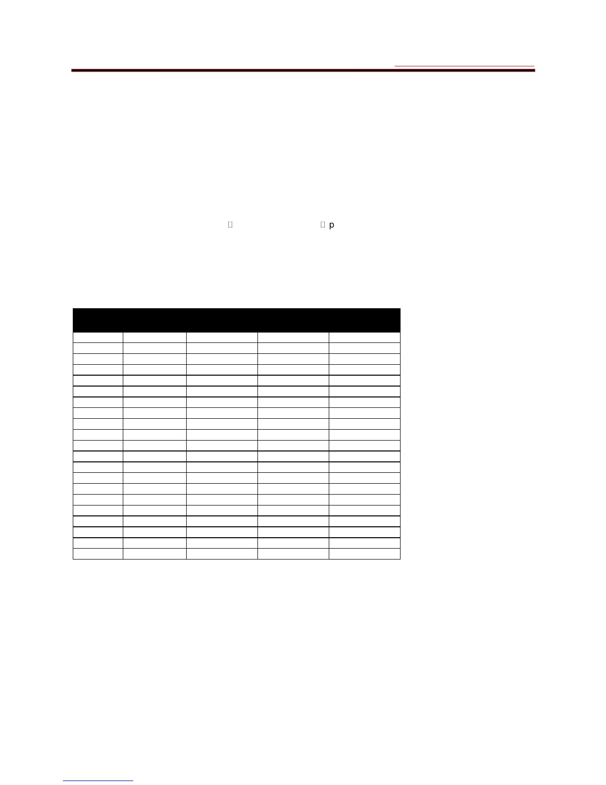
Table 4-1 shows RTD resistances for various temperatures. Individual, actual stator and bearing RTD temperatures
can be viewed in ACTUAL VALUES mode, page 2.
To test overtemperature trip/alarm functions the simulated RTD potentiometers should be adjusted to correspond to
high RTD temperatures.
Table 4-1 RTD Resistance vs. Temperature
RESISTANCE (IN OHMS)
TEMP °C
100
Ω
Pt 120
Ω
Ni 100
Ω
Ni 100
Ω
Cu
0 100.00 120.00 100.00 9.04
10 103.90 127.17 105.97 9.42
20 107.79 134.52 112.10 9.81
30 111.67 142.06 118.38 10.19
40 115.54 149.79 124.82 10.58
50 119.39 157.74 131.45 10.97
60 123.24 165.90 138.25 11.35
70 127.07 174.25 145.20 11.74
80 130.89 182.84 152.37 12.12
90 134.70 191.64 159.70 12.51
100 138.50 200.64 167.20 12.90
110 142.29 209.85 174.87 13.28
120 146.06 219.29 182.75 13.67
130 149.82 228.96 190.80 14.06
140 153.58 238.85 199.04 14.44
150 157.32 248.95 207.45 14.83
160 161.04 259.30 216.08 15.22
170 164.76 269.91 224.92 15.61
180 168.47 280.77 233.97 16.00
190 172.46 291.96 243.30 16.39
200 175.84 303.46 252.88 16.78
4.6 Power Failure Testing
When the AC voltage applied to the 169 relay decreases to below about 90 V the relay SERVICE L.E.D. should
become illuminated. All output relays will also go to their power down states. To test the memory circuitry of the
relay, remove and then re-apply control power. All stored setpoints and statistical data should be unchanged. The
displayed lock-out time after an overload trip should continue to decrease even when control power is removed.
 Loading...