3 SETUP AND USE
g
GE Power Management
26
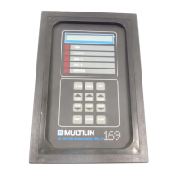
3.1 Controls and Indicators
Once the 169 relay has been wired and control power applied, it is ready to be programmed for the given application.
Programming is accomplished using the 12 position keypad and 48 character alphanumeric display shown in Figure
3-1. The function of each key on the keypad and each of the indicators is briefly explained in Table 3-1.
Table 3-1 Controls and Indicators
No. Name Description
FUNCTION:
The ACTUAL VALUES key allows the user to examine all of the actual motor
operating parameters. There are six pages of ACTUAL VALUES data:
•
page 1: Phase Current Data
•
page 2: RTD Temperature Data
•
page 3: Motor Capacity Data
•
page 4: Statistical Data
•
page 5: Pre-trip Data
•
page 6: Learned Parameters
1 ACTUAL
VALUES
EFFECT:
Pressing this key will put the relay into ACTUAL VALUES mode. The flash
message
ACTUAL VALUES HAS SIX
PAGES OF DATA
will be displayed for 2 seconds. The beginning of page 1 of ACTUAL VALUES mode will
then be shown:
PAGE 1: ACTUAL VALUES
PHASE CURRENT DATA
USE:
This key can be pressed at any time, in any mode to view actual motor values. To go
from page to page the PAGE UP and PAGE DOWN keys can be used. To go from line to
line within a page the LINE UP and LINE DOWN keys can be used.
2 SET
POINTS
FUNCTION:
The SET POINTS key allows the user to examine and alter all trip, alarm, and
other relay setpoints. There are six pages of setpoints data:
•
page 1: Motor Amps Setpoints
•
page 2: RTD Setpoints
•
page 3: O/L Curve Setpoints
•
page 4: Relay Configuration
•
page 5: System Configuration
•
page 6: Multilin Service Codes
 Loading...