3 SETUP AND USE
g
GE Power Management
70
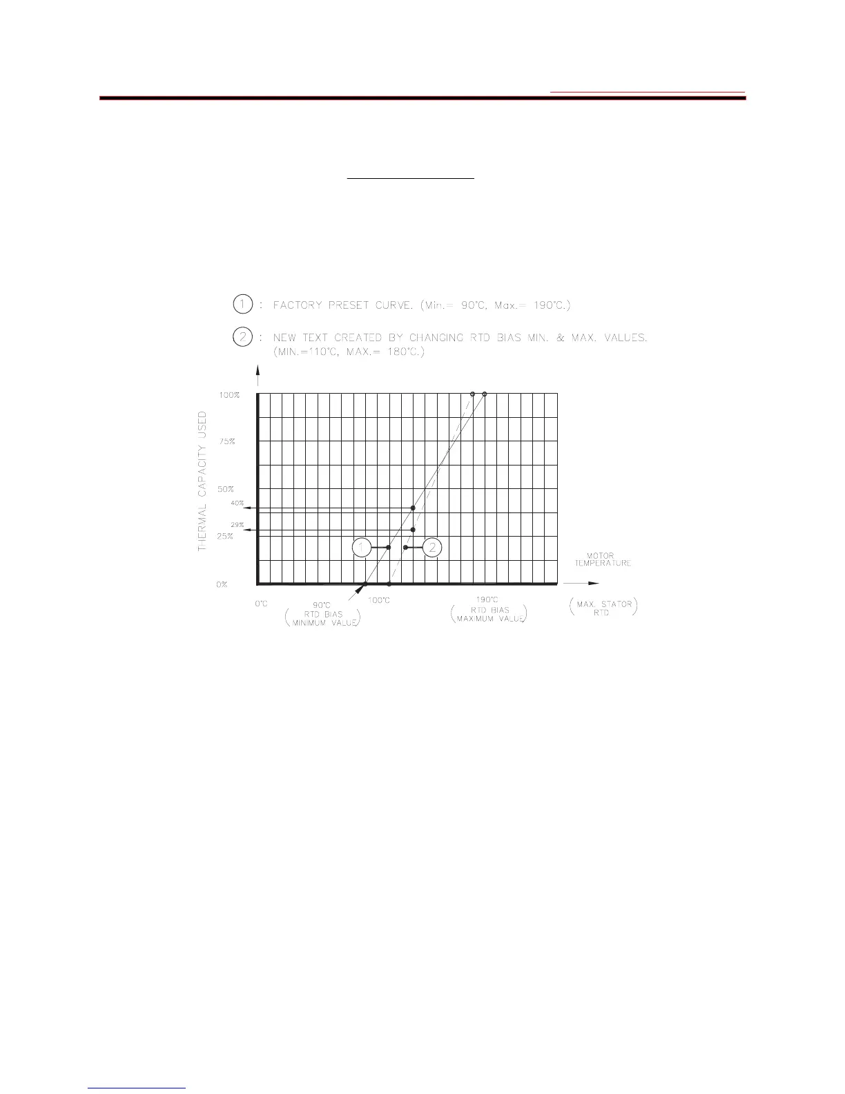
changed to correspond to curve 2 in Figure 3-4 the result will be somewhat different. The thermal capacity available
will be approximately 71% at 130 C. The thermal capacity available at any temperature between the RTD bias curve
minimum and maximum values can be determined from the graph or calculated as follows:
Min. RTDMax RTD
Min. RTDTemp
100100Capacity Thermal Average
−
−
×−=
where: Temp.= Hottest Stator RTD temperature
RTD Min. = RTD bias curve minimum value
RTD Max. = RTD bias curve maximum value
If the hottest stator RTD temperature is below the RTD bias curve minimum value the total thermal capacity available
will be 100%.
Figure 3-4 Hot Motor Thermal Capacity Reduction
The effect of reducing the thermal capacity available when the motor is hot is equivalent to shifting the overload
curve down resulting in a shorter time to trip. Using the example above when the total thermal capacity available is
reduced to 59% the trip time at any overload level will also be reduced to 59% of its original value.
LEARNED COOLING TIMES - Through various measurement and averaging techniques the 169 relay "learns" a
number of motor parameters. All learned values can be examined in page 6 of ACTUAL VALUES mode. If RTDs
are used to monitor the temperature of the motor stator the relay will learn the running and stopped cooling times of
the motor. In this way the 169 provides increased accuracy in the thermal modeling of the protected motor. When
RTD #8 (RTD #10 on the 169 Plus) is used for ambient air temperature monitoring even greater thermal protection is
provided since the cooling air temperature is known. In this case the learned cool times are based on the difference
between the ambient temperature and the average stator RTD temperature. When no ambient sensing is used the
learned cool times are based only on the average stator RTD temperature. If no stator RTDs are used, or if the
DEFEAT LEARNED COOL TIME setpoint (SETPOINTS mode, page 5) is left as "YES", the relay will use the default
times as described above.
Note: The learned cooling times should not be enabled until the 169 Plus relay has had sufficient time to
learn the actual motor cooling times. The time required will vary between motors, however several start/stop
cycles will be necessary.
The 169 Plus relay learns the motor cooling times over various temperature ranges. Thus the times shown in page 6
of ACTUAL VALUES mode (LEARNED RUNNING COOL TIME, LEARNED STOPPED COOL TIME) will reflect the
total cooling time as a combination of the cooling times over each temperature range.
 Loading...