Section 15 - Test Alarms
29
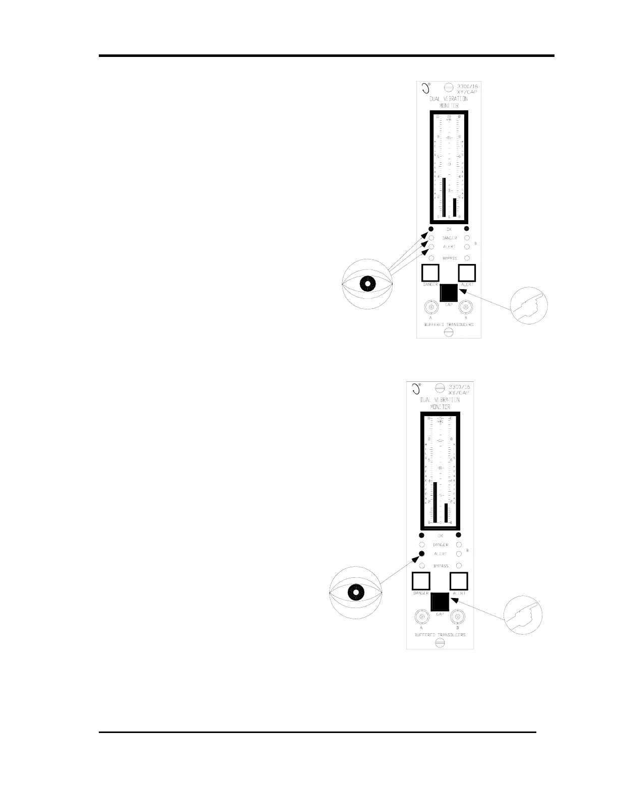
15.3 Test Gap Alarms
• If the Gap Full Scale Range option is in
engineering units instead of volts, this
section still applies with the exception that
the gap value will be referenced to zero
position at the center of the meter scale.
1. To test Gap alarms for Channel A, Press
the GAP switch and adjust the function
generator DC bias so that the Gap voltage
is within the gap alarm setpoint window
(See section 7 for viewing the gap Alert
setpoint window).
2. Press the RESET switch and verify that
the OK LEDs are on, and the ALERT and
DANGER LEDs are off.
3. Adjust the gap voltage on the monitor
to just exceed the Over Gap Alert
setpoint level and verify that the
ALERT LED comes on after the 6
second delay period has elapsed
(flashing if the First Out option is
selected).
• Verify that the Alert relay changed
state.
4. Press the RESET switch on the system
monitor and verify that the ALERT LED
remains on and steady.

 Loading...


