Section 16 - Test OK Limits
31
16. Test OK Limits
16.1 Test Equipment Setup
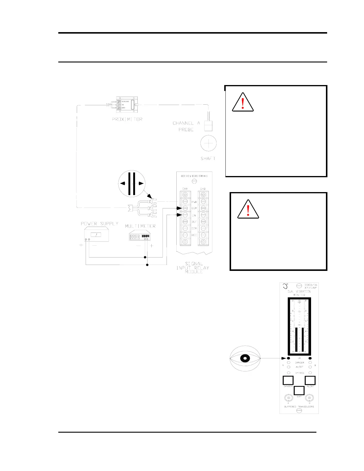
1. Disconnect the COM and IN wiring from the
channel A terminals on the Signal Input Relay
Module.
2. Connect the multimeter and the power supply to
channel A terminals as shown above.
3. Adjust the power supply voltage to -9 Vdc with
respect to common.
4. Verify that the channel A OK LED is on.
• In the event the function generator cannot supply the
necessary DC offset, a floating DC Power Supply
will need to be connected in series with the function
generator. Connect the positive terminals of the
function generator and power supply, connect the
negative terminal of the power supply to IN signal
and the negative terminal of the function generator
to the COM signal.
WARNING
High voltage present.
Contact could cause
shock, burns or death.
Do not touch exposed wires
or terminals.
Caution
Tests will exceed Gap Alert
setpoint levels and cause
alarms to activate (if
enabled). Relay contacts
may change state. See Main

 Loading...


