DigitalFlow™ Multipurpose Ultrasonic Liquid Flowmeter Service Manual 33
Chapter 4. Parts Replacement
4.7 Installing the Printed Circuit Board (cont.)
9. For LVD compliant units, position the clear plastic LVD shroud over the electrical connections so that the two
holes in the shroud align with the standoffs on the printed circuit board. Secure the shroud to the standoffs with the
two sets of screws and washers.
10. After carefully checking for and removing any loose hardware in the enclosure, close the electronics console and
reconnect the main power to the Model DF868.
Note: For compliance with the European Union’s Low Voltage Directive (73/23/EEC), this unit requires an external
power disconnect device such as a switch or circuit breaker. The disconnect device must be marked as such,
clearly visible, directly accessible, and located within 1.8 m (6 ft) of the Model DF868.
Before taking measurements with the Model DF868, refer to Chapter 2, Initial Setup, of the Startup Guide, and Chapter
1, Calibration, of this Service Manual for instructions on setting up the meter for accurate flow rate measurements.
Note: Be sure to enter a complete and detailed account of the service procedure performed on the Model DF868 in
Appendix A, Service Record.
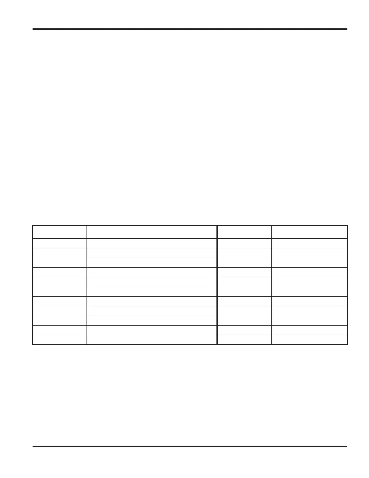
4.8 Spare Parts
All of the necessary components to upgrade or repair the Model DF868 flowmeter are readily available from GE. As a
convenient reference, some of the more common spare parts are listed below in Table 5.
To purchase the parts listed in Table 5 above or any items not listed in the table, contact the factory for assistance. To
make sure the proper components are obtained, be sure to specify the serial number of the Model DF868 at the time of
purchase.
Table 5: Spare Parts List
Part Number Description Part Number Description
703-1127-02 Option Card - Alarms, Hermetically Sealed 417-027 Card Guide, Nylon
703-1127-03 Option Card - Alarms, General Purpose 703-1247 Printed Circuit Board
703-1145-02 Option Card - Analog Inputs 705-1045 LCD Display Assembly
703-1126-02 Option Card - Analog Outputs 147-744 EPROM
703-1145-03 Option Card - RTD Inputs 421-700 Conduit Plate, 1/2”
703-1144-02 Option Card - Totalizer/Frequency Outputs 421-701 Conduit Plate, 3/4”
703-1358 Option Card - MODBUS 421-702 Conduit Plate, Blank
703-1476-02 Option Card - Ethernet Only 421-946 LVD Plastic Shroud
703-1476-05 Option Card - MODBUS over Ethernet 421-686 Main Aluminum Shroud
703-1476-10 Option Card - MODBUS over WI-FI 442-484 Label, Wiring Diagram
421-703 Card Cage (Metal Bracket)

 Loading...