EntelliGuard®TU Trip Unit
09/25/08 Section 1 – General Information
© 2008 General Electric All Rights Reserved 11
Table 5: Maximum Instantaneous Thresholds For
Power Break I, Power Break II, WavePro and AKR Trip
Units
Breaker
Frame Size
(A)
Maximum
Instantaneous
Threshold with
Short Time (× I
N
)
Maximum
Instantaneous
Threshold without
Short Time (× I
N
)
800
Off, 1.5 to 15 Off, 1.5 to 10
1600 Off, 1.5 to 15 Off, 1.5 to 10
2000 Off, 1.5 to 15 Off, 1.5 to 10
3200 Off, 1.5 to 13 Off, 1.5 to 10
4000 Off, 1.5 to 9 Off, 1.5 to 9
5000 Off, 1.5 to 7 Off, 1.5 to 7
Ground Fault Protection
The Trip Unit provides two types of ground fault
protection in addition to the GF alarm. These protections
are independent. The GF alarm has the same pickup level,
band choices and tolerances as GF.
The GF pickup value tolerance band is 15% the set point.
The ground fault pickup settings are listed in Table 6 as
multiples of xCT the current sensor rating, in steps of
0.01 xCT. The maximum value is limited to 1200.
Table 6: Ground Fault Pickup Settings
Protection
Type
Sensor, I
CT
Ground Fault Pickup
Threshold (× I
CT
)
GF SUM
GF SUM ALARM
GF CT
GT CT ALARM
150–2000 0.20–0.60 (max of 1200
A) (increment of 0.01)
with OFF as a selection
when GF or GF Alarm
Switchable is optioned.
GF/ALARM
Pickup
2500-3200 0.20–0.37 (increment of
0.01) with OFF as a
selection when GF or GF
Alarm Switchable is
optioned.
GF/ALARM
Pickup
4000 0.20–0.30 (increment of
0.01 with OFF as a
selection when GF or GF
Alarm Switchable is
optioned.
GF/ALARM
Pickup
5000 0.20–0.24 (increment of
0.01) with OFF as a
selection when GF or GF
Alarm Switchable is
optioned.
GF/ALARM
Pickup
6000 0.2 (1200 A) with OFF as
a selection when GF or
GF Alarm Switchable is
optioned.
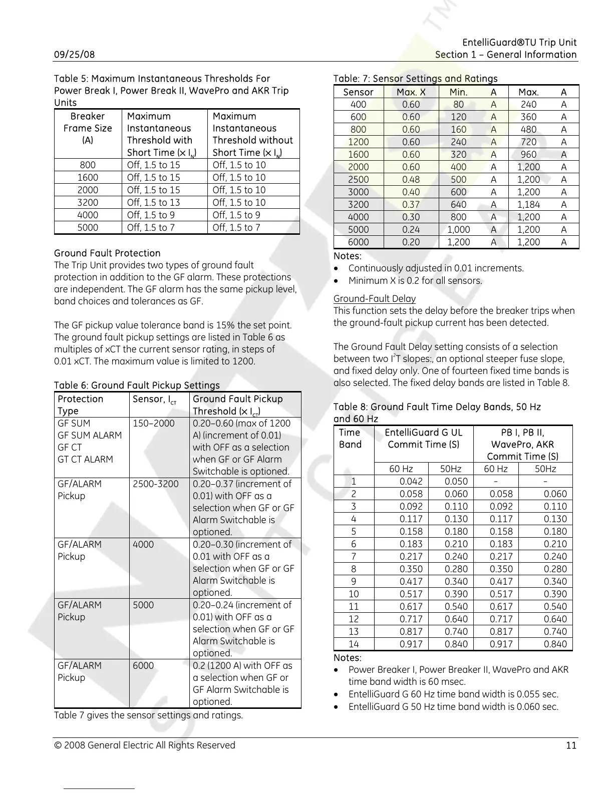
Table 7 gives the sensor settings and ratings.
Table: 7: Sensor Settings and Ratings
Sensor Max. X Min. A Max. A
400 0.60 80 A
240 A
600 0.60 120 A 360 A
800 0.60 160 A 480 A
1200 0.60 240 A 720 A
1600 0.60 320 A 960 A
2000 0.60 400 A 1,200 A
2500 0.48 500 A 1,200 A
3000 0.40 600 A 1,200 A
3200 0.37 640 A 1,184 A
4000 0.30 800 A 1,200 A
5000 0.24 1,000 A 1,200 A
6000 0.20 1,200 A 1,200 A
Notes:
• Continuously adjusted in 0.01 increments.
• Minimum X is 0.2 for all sensors.
Ground-Fault Delay
This function sets the delay before the breaker trips when
the ground-fault pickup current has been detected.
The Ground Fault Delay setting consists of a selection
between two I
2
T slopes:, an optional steeper fuse slope,
and fixed delay only. One of fourteen fixed time bands is
also selected. The fixed delay bands are listed in Table 8.
Table 8: Ground Fault Time Delay Bands, 50 Hz
and 60 Hz
EntelliGuard G UL
Commit Time (S)
PB I, PB II,
WavePro, AKR
Commit Time (S)
Time
Band
60 Hz 50Hz 60 Hz 50Hz
1 0.042 0.050
- -
2 0.058 0.060 0.058 0.060
3 0.092 0.110 0.092 0.110
4 0.117 0.130 0.117 0.130
5 0.158 0.180 0.158 0.180
6 0.183 0.210 0.183 0.210
7 0.217 0.240 0.217 0.240
8 0.350 0.280 0.350 0.280
9 0.417 0.340 0.417 0.340
10 0.517 0.390 0.517 0.390
11 0.617 0.540 0.617 0.540
12 0.717 0.640 0.717 0.640
13 0.817 0.740 0.817 0.740
14 0.917 0.840 0.917 0.840
Notes:
• Power Breaker I, Power Breaker II, WavePro and AKR
time band width is 60 msec.
• EntelliGuard G 60 Hz time band width is 0.055 sec.
• EntelliGuard G 50 Hz time band width is 0.060 sec.

 Loading...


