EntelliGuard® TU Trip Unit
Section 3 - Operation 09/25/08
22 © 2008 General Electric All Rights Reserved
Ground Fault Protection
The EntelliGuard TU Trip Unit can provide ground fault
protection in two different ways:
• via an internal summation scheme that adds up the
three phase current phasors, and if provided also the
neutral current phasor.
• Via an external zero sequence current signal from a
CT or a residual sum using iron core CTs.
Internal Residual Summation
The EntelliGuard trip unit uses internal air core sensors for
current sensing and the signals are residually summed
using advanced digital electronics. A neutral sensor may
be located remotely and connected to the trip unit. The
connection is limited to 10 m (33 ft).
Due to the air core sensor’s ability to handle a wide range
of primary currents without distortion, ground fault
sensing is accurate for a wide range of phase and current
inputs.
External Sensed Zero Sequence Input
The EntelliGuard trip unit can accept input from an externally
calculated ground fault current. The ground fault current
may be derived using a single zero sequence CT or multiple
phase CTs.
External CE marked zero sequence or ground return CTs
are available for IEC applications, but are not UL Listed.
Phase CTs used for a summation connection are UL
Listed. Applications for this capability include sensing at
the ground return connection for a transformer or
generator as well as application in multiple source
grounded systems.
Ground Fault Pickup Settings
All UL 489 and UL 1066 circuit breakers are limited to a
maximum nominal pick up setting of 1200 A per the
National Electrical Code or 60% of the sensor size,
whichever is lower. The minimum setting is 20% of sensor
size.
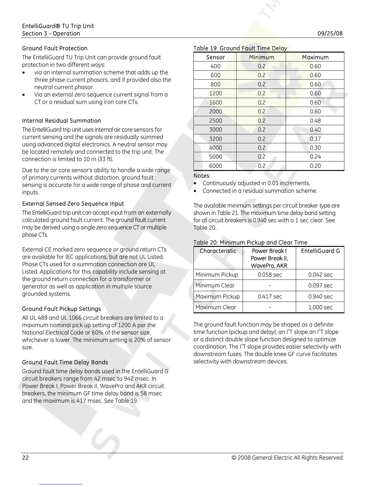
Ground Fault Time Delay Bands
Ground fault time delay bands used in the EntelliGuard G
circuit breakers range from 42 msec to 942 msec. In
Power Break I, Power Break II, WavePro and AKR circuit
breakers, the minimum GF time delay band is 58 msec
and the maximum is 417 msec. See Table 19.
Table 19: Ground Fault Time Delay
Sensor Minimum Maximum
400 0.2 0.60
600 0.2 0.60
800 0.2 0.60
1200 0.2 0.60
1600 0.2 0.60
2000 0.2 0.60
2500 0.2 0.48
3000 0.2 0.40
3200 0.2 0.37
4000 0.2 0.30
5000 0.2 0.24
6000 0.2 0.20
Notes:
• Continuously adjusted in 0.01 increments.
• Connected in a residual summation scheme.
The available minimum settings per circuit breaker type are
shown in Table 21. The maximum time delay band setting
for all circuit breakers is 0.940 sec with a 1 sec clear. See
Table 20.
Table 20: Minimum Pickup and Clear Time
Characteristic Power Break I
Power Break II,
WavePro, AKR
EntelliGuard G
Minimum Pickup 0.058 sec 0.042 sec
Minimum Clear
-
0.097 sec
Maximum Pickup 0.417 sec 0.940 sec
Maximum Clear
-
1.000 sec
The ground fault function may be shaped as a definite
time function (pickup and delay), an I
2
T slope an I
4
T slope
or a distinct double slope function designed to optimize
coordination. The I
4
T slope provides easier selectivity with
downstream fuses. The double knee GF curve facilitates
selectivity with downstream devices.

 Loading...


