EntelliGuard®TU Trip Unit
09/25/08 Section 2 – Lifting, Mounting and Installation
© 2008 General Electric All Rights Reserved 17
5. Remove the six ¼ hex head screws, securing the
escutcheon to the breaker (three at top and three at
bottom). Pull the manual-charging handle out part
way, and then slide off the escutcheon.
6. Pull out the locking side on the right of the trip unit
mounting plate, and then pull the trip unit out
carefully disengaging the pins on the rear connector.
7. Pull out the locking side on the right of the trip unit
mounting plate, and then pull the trip unit out
carefully disengaging the pins on the rear connector.
Reinstallation
1. Pull out the locking side on the right of the trip unit
mounting plate. Push the trip unit into place,
carefully, engaging the 50 pin connector and lining
up the rejection posts on the rear of the trip unit with
the holes in the mounting plate. Push the locking
slide to the left.
2. Ensure the breaker racking mechanism is still in the
TEST position. Pull the manual charging handle out
partway, and then slide the handle through the slot in
the escutcheon and move escutcheon into place.
Insert the six mounting screws and tighten to 14-20
in-lb.
3. Replace the trim plate around the escutcheon by
re-hooking the wire forms into the sides.
4. Insert the racking handle and return the racking
mechanism to the DISC position, as shown by the
draw-out position indicator.
5. Reinstall the circuit breaker into its cubical or
substructure.
AKR (225 A to 5000 A Frames) Circuit Breakers
1. Open the circuit breaker by pressing the red TRIP
button on the front of the breaker escutcheon.
2. Disconnect any secondary wire harnesses between
the breaker and the switchgear.
3. On draw-out breakers, rack the breaker all the way
out to the DISCONNECT position.
4. Follow the instructions on the label attached to the
PROGRAMMER RELEASE LEVER to remove the trip
unit. There are three types of mounting plates:
• Type 1: Push in the lever to release the trip unit.
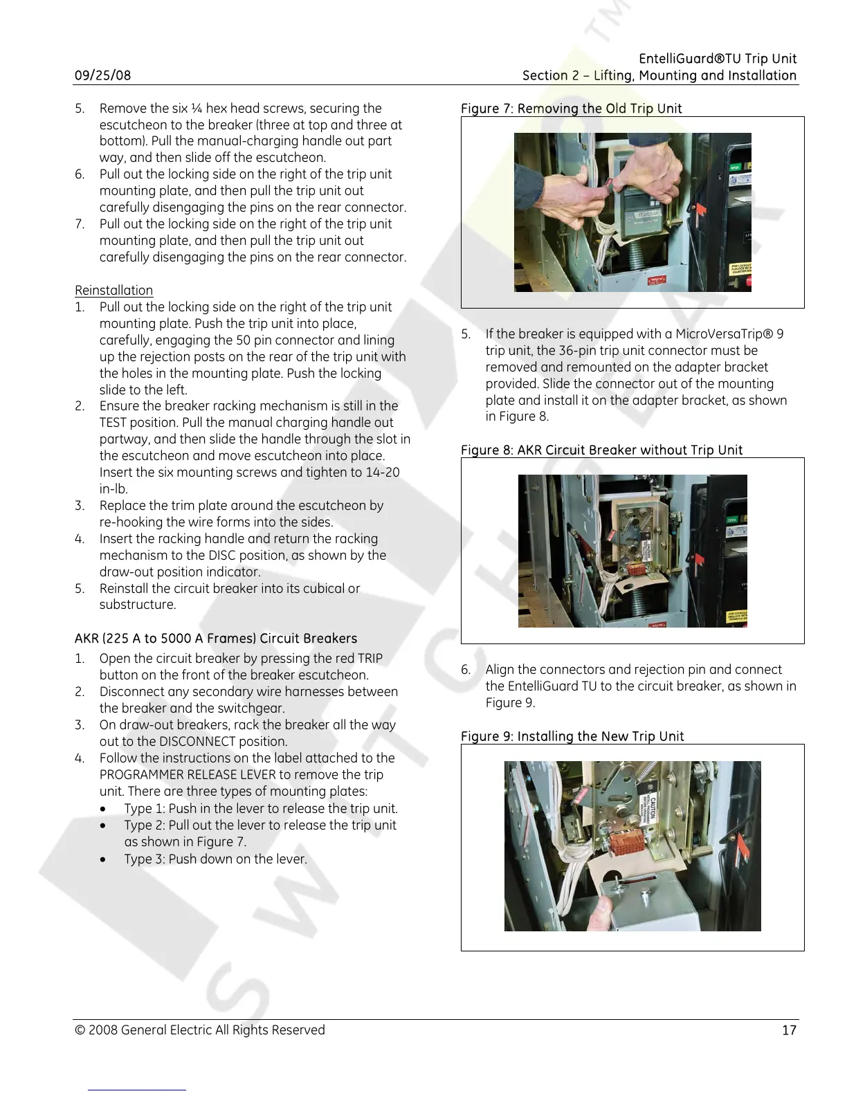
• Type 2: Pull out the lever to release the trip unit
as shown in Figure 7.
• Type 3: Push down on the lever.
Figure 7: Removing the Old Trip Unit
5. If the breaker is equipped with a MicroVersaTrip® 9
trip unit, the 36-pin trip unit connector must be
removed and remounted on the adapter bracket
provided. Slide the connector out of the mounting
plate and install it on the adapter bracket, as shown
in Figure 8.
Figure 8: AKR Circuit Breaker without Trip Unit
6. Align the connectors and rejection pin and connect
the EntelliGuard TU to the circuit breaker, as shown in
Figure 9.
Figure 9: Installing the New Trip Unit

 Loading...


