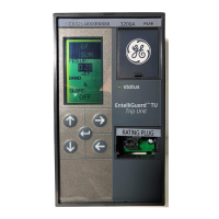
EntelliGuard® TU Trip Unit
Table of Contents 09/25/08
4 © 2008 General Electric All Rights Reserved
TABLE OF CONTENTS
SECTION 1 – GENERAL INFORMATION..........................................................................................................................................................7
INTRODUCTION .............................................................................................................................................................. 7
ABBREVIATIONS AND ACRONYMS........................................................................................................................ 7
PRODUCT DESCRIPTION ............................................................................................................................................ 7
Appearance................................................................................................................................................... 7
LCD Access..................................................................................................................................................... 7
Electrical Requirements .......................................................................................................................... 8
Equipment Interfaces............................................................................................................................... 8
COMMUNICATIONS ...................................................................................................................................................... 8
Modbus ............................................................................................................................................................ 8
ProfiBus............................................................................................................................................................ 9
OVER CURRENT PROTECTION FUNCTIONS ...................................................................................................... 9
Long Time ....................................................................................................................................................... 9
Short Time ...................................................................................................................................................... 9
Adjustable Selective Instantaneous Protection........................................................................10
Reduced Energy Let-Through Instantaneous Protection (RELT)......................................10
Ground Fault Protection........................................................................................................................11
PROTECTIVE RELAY.....................................................................................................................................................12
Voltage Unbalance Relay.....................................................................................................................12
Current Unbalance Relay .....................................................................................................................12
Under Voltage Relay ...............................................................................................................................12
Under Voltage Relay Zero-Volt Trip Enable ................................................................................12
Over Voltage Relay ..................................................................................................................................12
Power-Reversal Relay ............................................................................................................................12
Power Direction Setup ...........................................................................................................................12
Potential Transformer Primary Voltage........................................................................................12
Potential Transformer Connection..................................................................................................12
Power Demand Intervals......................................................................................................................13
Communication Address ......................................................................................................................13
Bell Alarm – Alarm Only/Bell Alarm with Lock-out Accessory Configuration Setup
(applies to Power Break II and WavePro Trip Units only).....................................................13
Settings Description ................................................................................................................................13
Input ................................................................................................................................................................13
Output.............................................................................................................................................................13
Current Alarm.............................................................................................................................................14
ZONE SELECT INTERLOCK .......................................................................................................................................14
ZSI Option .....................................................................................................................................................14
High Set Instantaneous Protection (HSIOC)................................................................................14
Making Current Release (MCR)...........................................................................................................14
POWER REQUIREMENTS ..........................................................................................................................................15
METERING FUNCTION ...............................................................................................................................................15
SECTION 2 – LIFTING, MOUNTING AND INSTALLATION.........................................................................................................................16
TRIP UNIT REMOVAL AND REPLACEMENT ......................................................................................................16
Power Break I and Power Break II Insulated Case Circuit Breakers ..............................16
WavePro Circuit Breakers ....................................................................................................................16
AKR (225 A to 5000 A Frames) Circuit Breakers........................................................................17
EntelliGuard Circuit Breaker Installation ......................................................................................18

 Loading...


