GE HEALTHCARE
DIRECTION 5245279, REVISION 3 LOGIQ™ P6/P6 PRO SERVICE MANUAL
Section 7-8 - LED Descriptions 7 - 25
Section 7-8
LED Descriptions
7-8-1 DTRX64II Assy
The DTRX64II Assys are located at the No.1 and No.2 slot in the NEST Assy.
7-8-2 PI128 II Assy (LOGIQ™ P6/P6 Pro)
The PI128 II Assy is located at the front of the NEST Assy.
7-8-3 P3RLY Assy (LOGIQ™ P6/P6 Pro PRO)
The P3RLY Assy is located at the front of the NEST Assy.
7-8-4 SYSCONML Assy
The SYSCONML Assy is located at the No.4 slot of the NEST Assy.
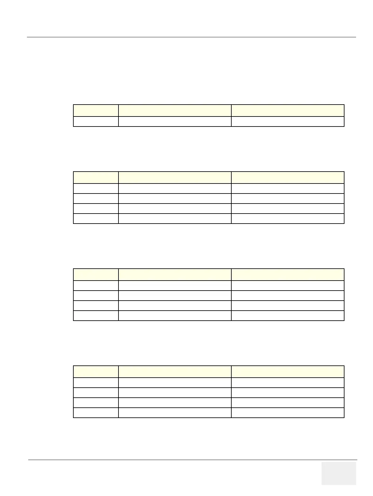
Table 7-10 LED on DTRX64II Assy
LED
Descriptions Normal State
DS1 FPGA configuration OK status Indicator Normally Blinking
Table 7-11 LEDs on PI128 II Assy
LED
Descriptions Normal State
D1 MUX embedded Probe Recognition Indicator Normally On
D2 Selected probe connector position number bit 0 Depend on live probe position
D3 Selected probe connector position number bit 1 Depend on live probe position
D4 FPGA Configuration OK status indicator Normally On
Table 7-12 LEDs on P3RLY/P2RLY Assy
LED
Descriptions Normal State
D1 MUX embedded Probe Recognition Indicator Normally On
D2 Selected probe connector position number bit 0 Depend on live probe position
D3 Selected probe connector position number bit 1 Depend on live probe position
D4 FPGA Configuration OK status indicator Normally On
Table 7-13 LEDs on L1SYSCON Assy
LED
Descriptions Normal State
DS1 CPDI FPGA configuration OK indicator Normally On
DS2 Frame Start signal. Scan running status indicator Normally blinking on scanning
DS3 FEBC FPGA configuration OK indicator Normally On
DS4 DSP operation OK indicator Normally blinking

 Loading...


