5–36 489 GENERATOR MANAGEMENT RELAY – INSTRUCTION MANUAL
CHAPTER 5: SETPOINTS
• ENABLE VOLTAGE RESTRAINT: “Yes”
•
VOLTAGE LOWER LIMIT: 10%
• Phase-Phase Voltage / Rated Phase-Phase Voltage = 0.4 p.u. V
The voltage restrained phase overcurrent pickup level is calculated as follows:
(EQ 5.9)
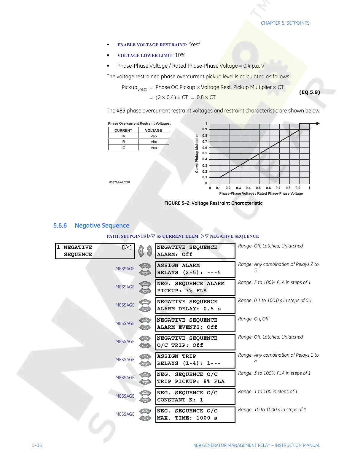
The 489 phase overcurrent restraint voltages and restraint characteristic are shown below.
FIGURE 5–2: Voltage Restraint Characteristic
5.6.6 Negative Sequence
PATH: SETPOINTS ZV S5 CURRENT ELEM. ZV NEGATIVE SEQUENCE
Pickup
vrest
Phase OC Pickup Voltage Rest. Pickup Multiplier CT××=
20.4×()CT×= 0.8 CT×=
808792A4.CDR
Phase-Phase Voltage / Rated Phase-Phase Voltage
Curve Pickup Multiplier
0
0 0.1 0.2 0.3 0.4 0.5 0.6 0.7 0.8 0.9 1
0.1
0.2
0.4
0.5
0.6
0.7
0.8
0.9
1
0.3
CURRENT VOLTAGE
IA Vab
IB Vbc
IC Vca
Phase Overcurrent Restraint Voltages:
1 NEGATIVE [Z]
SEQUENCE
NEGATIVE SEQUENCE
ALARM: Off
Range: Off, Latched, Unlatched
MESSAGE
ASSIGN ALARM
RELAYS (2-5): ---5
Range: Any combination of Relays 2 to
5
MESSAGE
NEG. SEQUENCE ALARM
PICKUP: 3% FLA
Range: 3 to 100% FLA in steps of 1
MESSAGE
NEGATIVE SEQUENCE
ALARM DELAY: 0.5 s
Range: 0.1 to 100.0 s in steps of 0.1
MESSAGE
NEGATIVE SEQUENCE
ALARM EVENTS: Off
Range: On, Off
MESSAGE
NEGATIVE SEQUENCE
O/C TRIP: Off
Range: Off, Latched, Unlatched
MESSAGE
ASSIGN TRIP
RELAYS (1-4): 1---
Range: Any combination of Relays 1 to
4
MESSAGE
NEG. SEQUENCE O/C
TRIP PICKUP: 8% FLA
Range: 3 to 100% FLA in steps of 1
MESSAGE
NEG. SEQUENCE O/C
CONSTANT K: 1
Range: 1 to 100 in steps of 1
MESSAGE
NEG. SEQUENCE O/C
MAX. TIME: 1000 s
Range: 10 to 1000 s in steps of 1
Courtesy of NationalSwitchgear.com
 Loading...


