CHAPTER 2: INTRODUCTION
489 GENERATOR MANAGEMENT RELAY – INSTRUCTION MANUAL 2–5
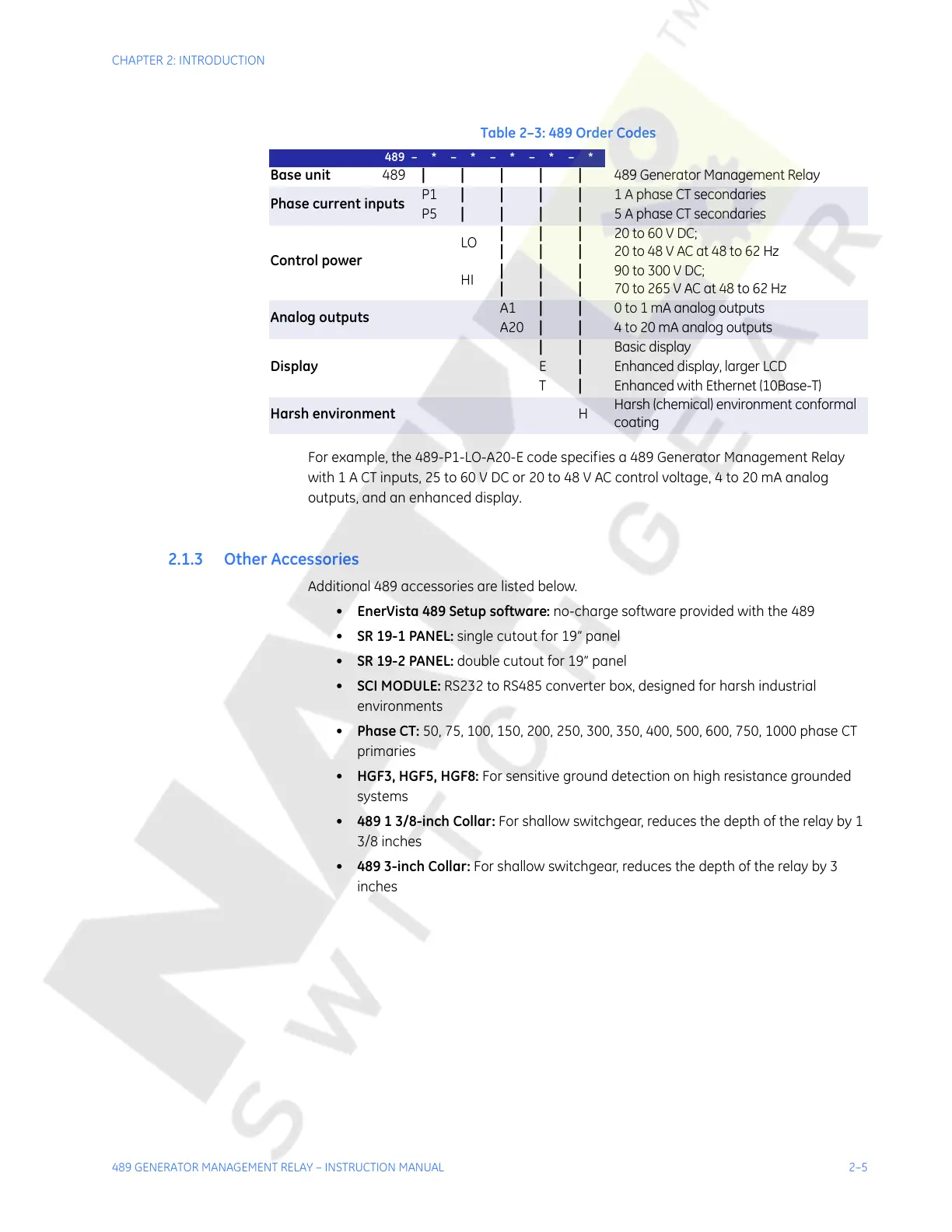
For example, the 489-P1-LO-A20-E code specifies a 489 Generator Management Relay
with 1 A CT inputs, 25 to 60 V DC or 20 to 48 V AC control voltage, 4 to 20 mA analog
outputs, and an enhanced display.
2.1.3 Other Accessories
Additional 489 accessories are listed below.
• EnerVista 489 Setup software: no-charge software provided with the 489
• SR 19-1 PANEL: single cutout for 19” panel
• SR 19-2 PANEL: double cutout for 19” panel
• SCI MODULE: RS232 to RS485 converter box, designed for harsh industrial
environments
• Phase CT: 50, 75, 100, 150, 200, 250, 300, 350, 400, 500, 600, 750, 1000 phase CT
primaries
• HGF3, HGF5, HGF8: For sensitive ground detection on high resistance grounded
systems
• 489 1 3/8-inch Collar: For shallow switchgear, reduces the depth of the relay by 1
3/8 inches
• 489 3-inch Collar: For shallow switchgear, reduces the depth of the relay by 3
inches
Table 2–3: 489 Order Codes
489 – * – * – * – * – *
Base unit
489 |||||
489 Generator Management Relay
Phase current inputs
P1 | | | |
1 A phase CT secondaries
P5 | | | |
5 A phase CT secondaries
Control power
LO
|
|
|
|
|
|
20 to 60 V DC;
20 to 48 V AC at 48 to 62 Hz
HI
|
|
|
|
|
|
90 to 300 V DC;
70 to 265 V AC at 48 to 62 Hz
Analog outputs
A1 | |
0 to 1 mA analog outputs
A20 | |
4 to 20 mA analog outputs
Display
||
Basic display
E |
Enhanced display, larger LCD
T |
Enhanced with Ethernet (10Base-T)
Harsh environment
H
Harsh (chemical) environment conformal
coating
Courtesy of NationalSwitchgear.com
 Loading...


