7–14 489 GENERATOR MANAGEMENT RELAY – INSTRUCTION MANUAL
CHAPTER 7: TESTING
REACTIVE POWER ALARM: “Unlatched”
ASSIGN ALARM RELAYS(2-5): “---5”
POSTIVE MVAR ALARM LEVEL: “0.6 x Rated”
NEGATIVE MVAR ALARM LEVEL: “0.6 x Rated”
REACTIVE POWER ALARM DELAY: “5 s”
REACTIVE POWER ALARM EVENT: “On”
REACTIVE POWER TRIP: “Unlatched”
ASSIGN TRIP RELAYS(1-4): “1---”
POSTIVE MVAR TRIP LEVEL: “0.75 x Rated”
NEGATIVE MVAR TRIP LEVEL: “0.75 x Rated”
REACTIVE POWER TRIP DELAY: “10 s”
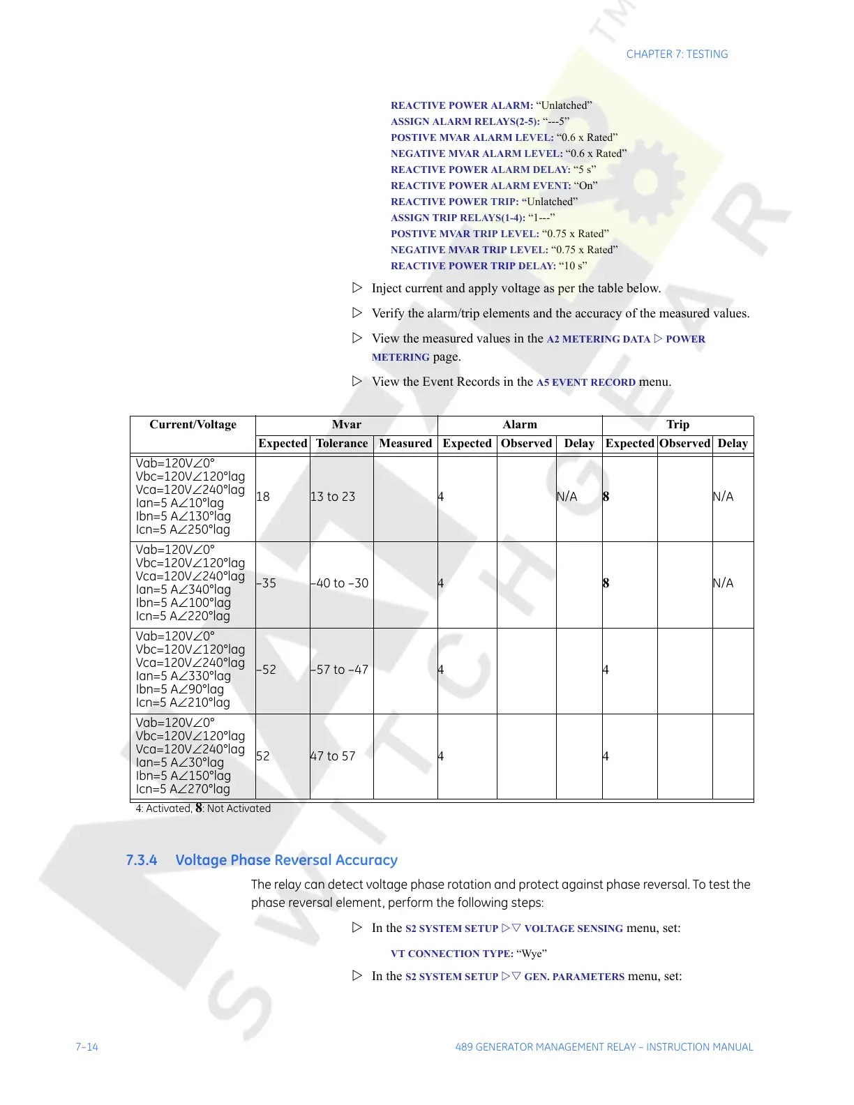
Z Inject current and apply voltage as per the table below.
Z Verify the alarm/trip elements and the accuracy of the measured values.
Z View the measured values in the
A2 METERING DATA Z POWER
METERING
page.
Z View the Event Records in the
A5 EVENT RECORD menu.
7.3.4 Voltage Phase Reversal Accuracy
The relay can detect voltage phase rotation and protect against phase reversal. To test the
phase reversal element, perform the following steps:
Z In the
S2 SYSTEM SETUP ZV VOLTAGE SENSING menu, set:
VT CONNECTION TYPE: “Wye”
Z In the S2 SYSTEM SETUP ZV GEN. PARAMETERS menu, set:
Current/Voltage Mvar Alarm Trip
Expected Tolerance Measured Expected Observed Delay Expected Observed Delay
Vab=120V∠0°
Vbc=120V∠120°lag
Vca=120V∠240°lag
Ian=5 A∠10°lag
Ibn=5 A∠130°lag
Icn=5 A∠250°lag
18 13 to 23 4 N/A
8
N/A
Vab=120V∠0°
Vbc=120V∠120°lag
Vca=120V∠240°lag
Ian=5 A∠340°lag
Ibn=5 A∠100°lag
Icn=5 A∠220°lag
–35 –40 to –30 4
8
N/A
Vab=120V∠0°
Vbc=120V∠120°lag
Vca=120V∠240°lag
Ian=5 A∠330°lag
Ibn=5 A∠90°lag
Icn=5 A∠210°lag
–52 –57 to –47 44
Vab=120V∠0°
Vbc=120V∠120°lag
Vca=120V∠240°lag
Ian=5 A∠30°lag
Ibn=5 A∠150°lag
Icn=5 A∠270°lag
52 47 to 57 44
4: Activated, 8: Not Activated
Courtesy of NationalSwitchgear.com
 Loading...


