7–4 489 GENERATOR MANAGEMENT RELAY – INSTRUCTION MANUAL
CHAPTER 7: TESTING
7.2 Hardware Functional Tests
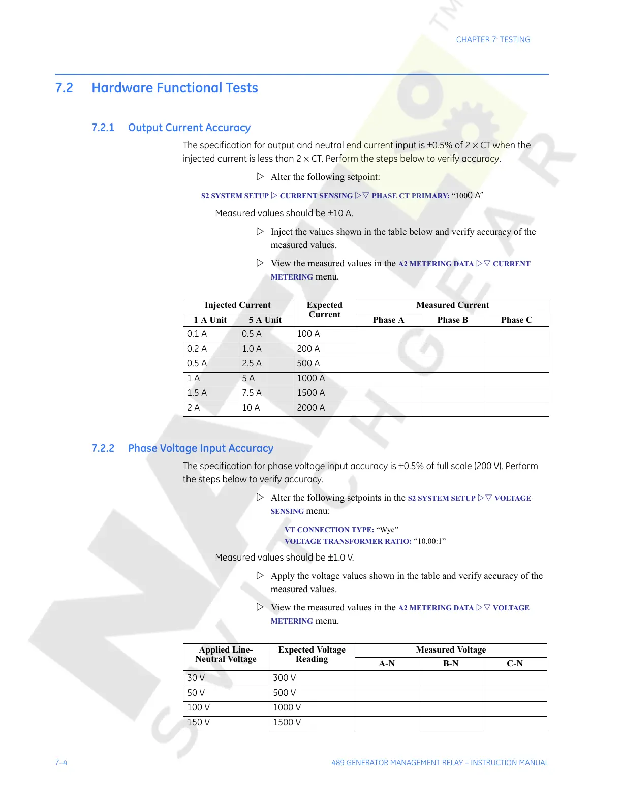
7.2.1 Output Current Accuracy
The specification for output and neutral end current input is ±0.5% of 2 × CT when the
injected current is less than 2 × CT. Perform the steps below to verify accuracy.
Z Alter the following setpoint:
S2 SYSTEM SETUP Z CURRENT SENSING ZV PHASE CT PRIMARY: “1000A”
Measured values should be ±10 A.
Z Inject the values shown in the table below and verify accuracy of the
measured values.
Z View the measured values in the
A2 METERING DATA ZV CURRENT
METERING
menu.
7.2.2 Phase Voltage Input Accuracy
The specification for phase voltage input accuracy is ±0.5% of full scale (200 V). Perform
the steps below to verify accuracy.
Z Alter the following setpoints in the
S2 SYSTEM SETUP ZV VOLTAGE
SENSING
menu:
VT CONNECTION TYPE: “Wye”
VOLTAGE TRANSFORMER RATIO: “10.00:1”
Measured values should be ±1.0 V.
Z Apply the voltage values shown in the table and verify accuracy of the
measured values.
Z View the measured values in the
A2 METERING DATA ZV VOLTAGE
METERING menu.
Injected Current Expected
Current
Measured Current
1A Unit 5A Unit Phase A Phase B Phase C
0.1 A 0.5 A 100 A
0.2 A 1.0 A 200 A
0.5 A 2.5 A 500 A
1 A 5 A 1000 A
1.5 A 7.5 A 1500 A
2 A 10 A 2000 A
Applied Line-
Neutral Voltage
Expected Voltage
Reading
Measured Voltage
A-N B-N C-N
30 V 300 V
50 V 500 V
100 V 1000 V
150 V 1500 V
Courtesy of NationalSwitchgear.com
 Loading...


