3–2 489 GENERATOR MANAGEMENT RELAY – INSTRUCTION MANUAL
CHAPTER 3: INSTALLATION
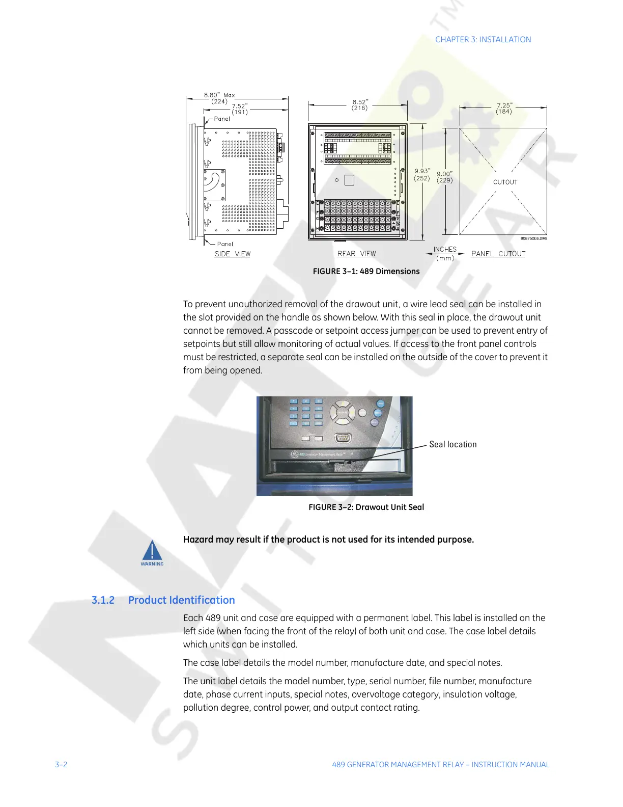
FIGURE 3–1: 489 Dimensions
To prevent unauthorized removal of the drawout unit, a wire lead seal can be installed in
the slot provided on the handle as shown below. With this seal in place, the drawout unit
cannot be removed. A passcode or setpoint access jumper can be used to prevent entry of
setpoints but still allow monitoring of actual values. If access to the front panel controls
must be restricted, a separate seal can be installed on the outside of the cover to prevent it
from being opened.
FIGURE 3–2: Drawout Unit Seal
Hazard may result if the product is not used for its intended purpose.
3.1.2 Product Identification
Each 489 unit and case are equipped with a permanent label. This label is installed on the
left side (when facing the front of the relay) of both unit and case. The case label details
which units can be installed.
The case label details the model number, manufacture date, and special notes.
The unit label details the model number, type, serial number, file number, manufacture
date, phase current inputs, special notes, overvoltage category, insulation voltage,
pollution degree, control power, and output contact rating.
Courtesy of NationalSwitchgear.com
 Loading...


