16
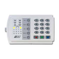
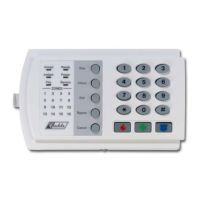
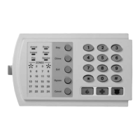
NX-6V2 Control
Segment 2:
1 = On enables the LED Extinguish feature.
2 = On enables the Require Code for Bypassing feature.
3 = On enables the Zone Bypassed Sounder Alert feature.
4 = On enables the AC Power/Low Battery Sounder Alert feature.
5 = On enables Bypass toggle.
6 = On enables Silent Auto Arm.
7 = On enables the Automatic Instant feature.
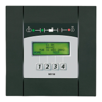
8 = On enables Instant mode toggle. (Applies to NX-1208E / NX-1248E keypads)
Segment 3:
1 = On enables Opening and Closing reports.
2 = On enables Zone Bypass reporting.
3 = On enables Zone Restore reporting.
4 = On enables Zone Trouble reporting.
5 = On enables Zone Tamper reporting.
6 = On enables the Cancel reporting.
7 = On enables the Recent Closing report.
8 = On enables the Exit Error report.
Segment 4:
1 = On enables Late to Close / Early to Open.
2 = On enables Auto Arm in Stay Mode.
3 = On disables the door delays in Night mode. (Applies to NX-1208E / NX-1248E keypads)
4 - 8 = Reserved.
Segment 5: Reserved
L 24 ENTRY / EXIT TIMERS 6 ............ numerical
Location 24 is used to program the Entry/Exit times. There are 2 separate Entry/Exit times.
Segment 1, Entry time 1: This is the entry time that will be used when a delay 1 zone type initiates an entry delay. Valid
entries are 30-255 seconds.
Segment 2, Exit time 1: This is the exit time that will be used for all zones designated as delay 1. Valid entries are 45-255
seconds.
Segment 3, Entry time 2: This is the entry time that will be used when a delay 2 zone type initiates an entry delay. Valid
entries are 30-255 seconds.
Segment 4, Exit time 2: This is the exit time that will be used for all zones designated as delay 2. Valid entries are 45-255
seconds.
Segments 5 & 6 Reserved.
XIII. DEFAULT ZONE TYPES (Configurations)
Zones can be programmed to be one of thirty different zone types (configurations). Zone types 17 - 20 can be used for wireless or
hardwired zones using European double EOL configuration. The default zone types are listed below. These zone types can be
customized by programming locations 110-169.
DATA DESCRIPTION OF DEFAULT ZONE TYPES
1 DAY ZONE - Instant when system is armed trouble zone when system is disarmed.
2 24-HOUR AUDIBLE - Creates an instant yelping siren alarm regardless of the armed state of the control panel.
3
ENTRY/EXIT DELAY 1- A trip will start entry delay 1. The lack of a trip during exit delay will enable the Automatic
Bypass or Instant mode if so programmed.
4
FOLLOWER WITH AUTO- BYPASS DISABLED - This zone will be instant when the system is armed and no entry or
exit delays are being timed. It is delayed during entry and exit delay 1 times. This zone will not automatically bypass even
if enabled in Segment 1 of Location 23.
5
INTERIOR FOLLOWER WITH AUTO- BYPASS ENABLED - This zone will be instant when the system is armed and no
entry or exit delay is being timed. It is delayed during entry and exit delay 1 times. This zone will automatically bypass if
enabled in Segment 1 of Location 23.
6 INSTANT - This zone creates an instant alarm whenever it is tripped and the Armed LED is on.
7
24-HOUR SILENT - Creates an instant silent alarm regardless of the armed state of the control panel. It will not display
on the keypad.
8
FIRE - This zone will light the Fire LED and sound the temporal siren each time the zone is shorted. It will also rapidly
flash the Fire LED indicating a trouble if the zone is open.
 Loading...
