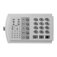
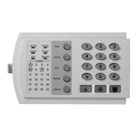
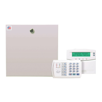
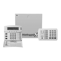
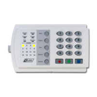
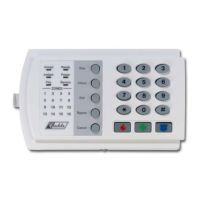
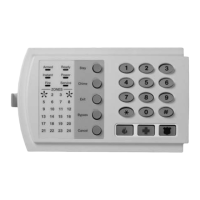
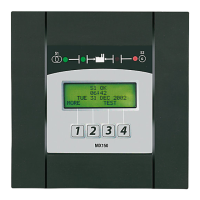
NX-6V2 Control 19
Segment 4:
1 = On if Fail To Communicate report enabled.
2 = On if Log Full report enabled.
3 = On if Autotest report enabled.
4 = On if Start/End programming report enabled.
5 = On if End Download report enabled.
6 = On if Sensor Low Battery report enabled.
7 = On if Sensor Missing report enabled.
8 = On if First to Open / Last to Close.
Segment 5:
1 = On enable Lost Clock service light.
2 = On enables Zone Doubling (requires NX-200 Zone Doubling Kit).
3 = On disables On-Board 6 zones.
4 = On will allow two trips on same cross-zone to activate an alarm.
5 = On will not allow zones that are force armed to report bypass.
6 = Reserved.
7 = Use internal crystal for clock.
8 = Disable Temporal Siren on Fire. NOTE: Do NOT disable for UL listed systems.
Segment 6:
1 = Enable 2 wire smoke.
2 = Reserved.
3 = Enable for Zone Activity in Hours (not Days)
4 = Enable Daylight Savings Time (DST)
5 = Reserved
6 = On to disable Clean Me report (At default, bit is OFF = enabled)
7 = On to disable Start/End Test report (At default, bit is OFF = enabled)
8 = Reserved.
Segment 7: Reserved
L 38 SWINGER SHUTDOWN COUNT 1............. numerical
Location 38 contains the number of trips during an arming cycle that the NX-6V2 will allow before bypassing a zone. The count
determination is described in the Glossary. Factory default is 1.
L 39 KEYPAD SOUNDER CONTROL 1............. feature select
Segment 1:
1 = On if keypad sounds for ATelephone Line Cut@ when the system is armed.
2 = On if keypad sounds for ATelephone Line Cut@ when disarmed.
3 = On if keypad sounds upon AC Power Failure.
4 = On if keypad sounds when a Low Battery is detected.
5 = On if keypad sounds during Cross Zone trip time.
6 = On if keypad sounds for zone and box tampers.
7 = Reserved.
8 = On if keypad sounds for expander trouble (required for UL installations).
L 40 SYSTEM TIMERS 14...........numerical
Location 40 contains the duration of various system timing functions. Example: If you desire the duration of the Dynamic Battery Test
to be 30 minutes, you should program [3]-[0]-[r] in segment 1 of this location. The [3]-[0] is the number of minutes, and the [r] stores
the data and moves to the next segment of this location.
NOTES FOR UL INSTALLATIONS
The "Listen-In" feature cannot be enabled for UL Listed systems.
The "Dynamic Battery Test" feature cannot exceed four (4) hours.
The dial delay shall be set to -0-.
Segment 1 - Dynamic Battery Test duration in minutes 0-255 minutes..................................... (0 = no test)
Segment 2 - AC Fail report delay in minutes 0-255 minutes. .................................................... (0 = no delay)
Segment 3 - Power Up Delay in seconds 0-60 seconds ...........................................................(0 = no power up delay)
Segment 4 - Siren Time in minutes 1-254 minutes.
Segment 5 - Telephone Line Cut delay in seconds 0-255 seconds........................................... (0 = no TLM)
Segment 6 - Cross Zone time in minutes 0-255 ........................................................................ (0 = no cross zoning)
Segment 7 - Chime time in 50 mS (1/20th second) increments from 0-12 seconds.................. (0 = follows zone 255 latched)
Segment 8 - Dial delay in seconds 15-255 seconds
 Loading...
