10 NX-
To Exit a Location:
#
Exits from this location. The “Ready” LED will extinguish. The "Armed"
LED will illuminate waiting for a new programming location to be
entered.
To Review The Data:
[location] #
The Armed LED will flash. If the location number is valid, the "Armed"
LED will extinguish, the "Ready" LED will illuminate, and the zone LEDs
will show the binary data for the first segment of this location.
(Do not enter data.)
The next segment is displayed. Each time
r is pressed, the data of the
next segment will be displayed for review.
Shortcuts:
Previous location.
Same location.
Next sequential location.
4. Exiting the Program Mode:
EXIT
Exits this programming level.
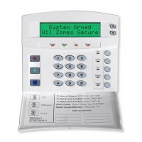
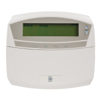
I.B. USING THE LCD KEYPAD
All steps required for programming are the same as the aforementioned LED keypad. The LCD keypad display
will prompt you for the data required. While in the programming mode, and not in a location, the number in
parenthesis is the location you were previously changing. For example, if the display reads, "Enter location,
then # (5)", it is reminding you that location 5 was the last location you programmed. Refer also to
"Programming Data" which follows.
I.C. PROGRAMMING DATA
Programming data is always one of three types. One type of data is numerical, which can take on values from 0
-15, 0 - F, or 0 -255 depending on the segment size. The other type of data, feature selection data, is used to
turn features on/off. Use the following procedures with these data types:
1. Numerical Data
Numerical data is programmed by entering a number from 0-255 on the numeric keys of the system
keypad. To view the data in a location, a binary process is used. With this process, the LED=s for zones 1
through 8 are utilized, and the numeric equivalents of their illuminated LED=s are added together to
determine the data in a programming location. The numeric equivalents of these LED=s are as follows:
Zone 1 LED = 1 Zone 3 LED = 4 Zone 5 LED = 16 Zone 7 LED = 64
Zone 2 LED = 2 Zone 4 LED = 8 Zone 6 LED = 32 Zone 8 LED = 128