NX-320E Power Supply 11
Example: If the numerical data to be programmed in a location is "66", press [6]-[6] on the keypad. The
LED=s for Zone 2 and Zone 7 will become illuminated indicating 66 is in that location (2 + 64 = 66). Once
the data is programmed, press [r] to enter the data and advance to the next segment of that location.
After the last segment of a location is programmed, pressing [r] will exit that location, turn the "Ready"
LED off, and the "Armed" LED on. As before, you are now ready to enter another programming location. If
an attempt is made to program a number too large for a particular segment, the keypad sounder will emit a
triple beep, indicating an error, and remain in that segment awaiting a valid entry.
2. Feature Selection Data
Feature selection data will display the current condition (on or off) of eight features associated with the
programming location and segment selected. Pressing a button on the touchpad (1 thru 8) that
corresponds to the "feature number" within a segment will toggle (on/off) that feature. Pressing any
numeric key between [1] and [8] for selection of a feature will make the corresponding LED illuminate
(feature ON). Press the number again, and the LED will extinguish (feature OFF). You will see that
numerous features can be selected from within one segment. For instance, if all eight features of a
segment are desired, pressing [1]-[2]-[3]-[4]-[5]-[6]-[7]-[8] will turn on LED's 1 thru 8 as you press the keys,
indicating that those features are enabled. LCD Keypad Users Note
: The numbers of the enabled features
will be displayed. However, the features not enabled will display a hyphen (-). After the desired setting
of features is selected for this segment, press [r]. This will enter the data and automatically advance to the
next segment of the location. When you are in the last segment of a location and press [r] to enter the
data, you will exit that location. This will now turn the "Ready" LED off and the "Armed" LED on. You are
now ready to enter another programming location.
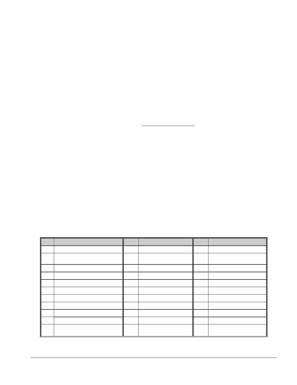
LOCATION 0 PROGRAMMING EVENT & TIME FOR OUTPUT A
(2 segments of numerical data)
Segment 1 is used to select the particular event that will trigger Output A. See following chart for the specific
events that can be selected.
Segment 2 is used to select the amount of time an output will remain activated when an output triggers. If this
location is programmed as a zero, the output will follow the particular event.
Table XII:1
#
Event
#
Event
#
Event
0
Always On
11 Smoke Power Reset 22 Disarmed
1
AC Fail (control or exp.)
Does not
follow AC Fail delay time
12 Yelping Siren 23 Ready to Arm
2
Low Battery (control or exp.) 13 Steady Siren 24 Not Ready to Arm
3
Dynamic Battery Test Time 14 Any Siren 25 Fire
4
Listen In 15 Steady Siren (temporal) 26 Fire Trouble
5
Line Seizure 16 Any Siren (temporal) 27 Chime
6
Telephone Line Fault 17 Alarm Memory 28 Beeping Keypad
7
Program Mode 18 Entry
29
Aux 1 Keypad Function
8
Over-current (control or exp.) 19 Exit
30
Aux 2 Keypad Function
9
Box Tamper (control or exp.) 20 Entry or Exit
31
Panic Keypad Function
10
Siren Tamper (control or exp.) 21 Armed
32
Code Entry
(set codes in loc
8 – 17)
If set to follow condition, these events will be one second.

 Loading...