8 NX-
IX. ADDRESSING
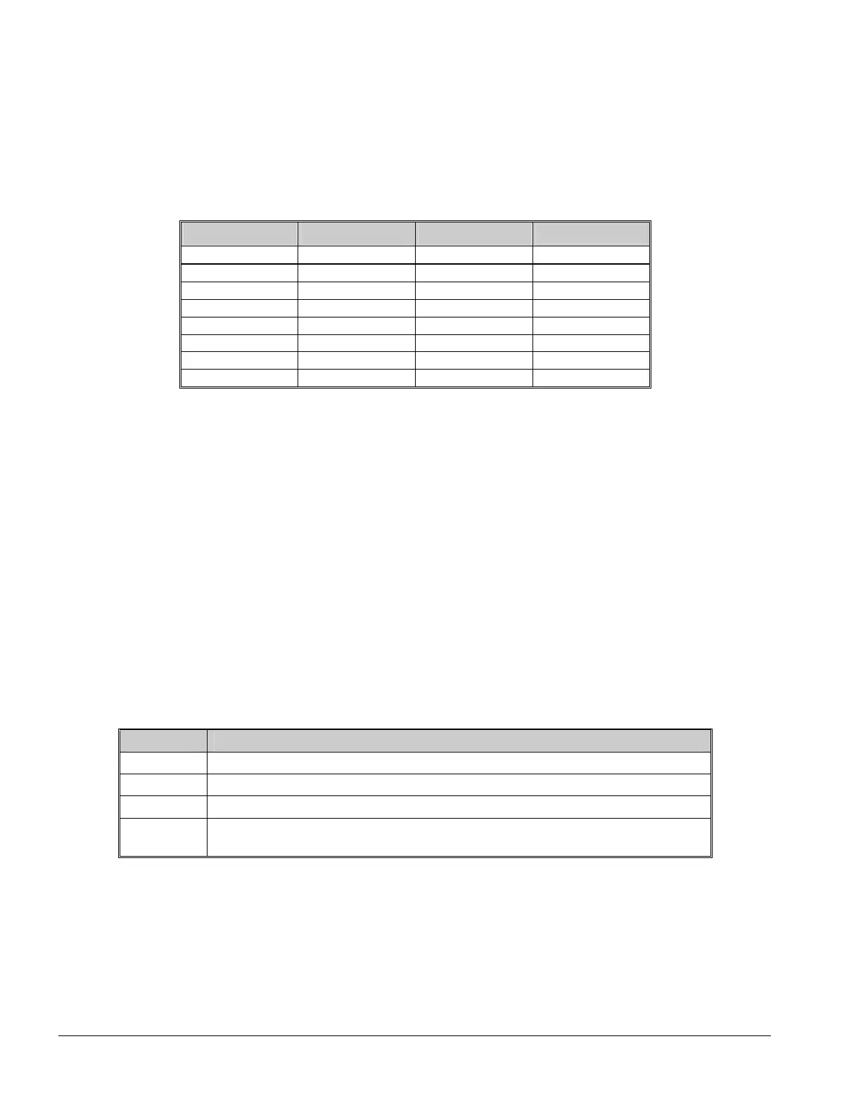
The first thing that must be decided is the address of this particular power supply. This is the address that will be
selected when programming the module. To set the address, use the table below.
Dip Switch 4 is used to disable the Tamper feature (“On = enabled / “Off” = disabled).
Table IX:1
Address
Dip switch 1
Dip switch 2
Dip switch 3
84 OFF OFF OFF
85 ON OFF OFF
86 OFF ON OFF
87 ON ON OFF
88 OFF OFF ON
89 ON OFF ON
90 OFF ON ON
91 ON ON ON
X. ENROLLING
The NX-8 / NX-8E / NX-8-CF has the ability to automatically find and store in its memory the presence of all keypads,
zone expanders, wireless receivers and any other module connected to the data terminal. This allows these
modules to be supervised by the control panel. To enroll the modules enter the Program Mode of the NX-8 / NX-8E /
NX-8-CF control panel, and when the Program Mode is exited, it will automatically enroll the devices. The enrolling
process takes about 12 seconds, during which time the “Service” LED will illuminate. User codes will not be
accepted during the enrolling process. Once a module is enrolled, if it is not detected by the control, the “Service”
LED will illuminate.
XI. UNDERSTANDING THE LEDS
The power supply module has four (4) red LEDs, which provide valuable information about its status. The following
chart furnishes the indications of each LED.
Table XI:1
LED Description
DS1 Flashes when data is transmitted out from the NX-320E.
DS2 Flashes when data is transmitted into the NX-320E.
DS3 Flashes during normal operation.
DS4
Used for hardware, and will only glow dimly when connected to the NX-8 / NX-
8E / NX-8-CF control panel.

 Loading...