NX-320E Power Supply 7
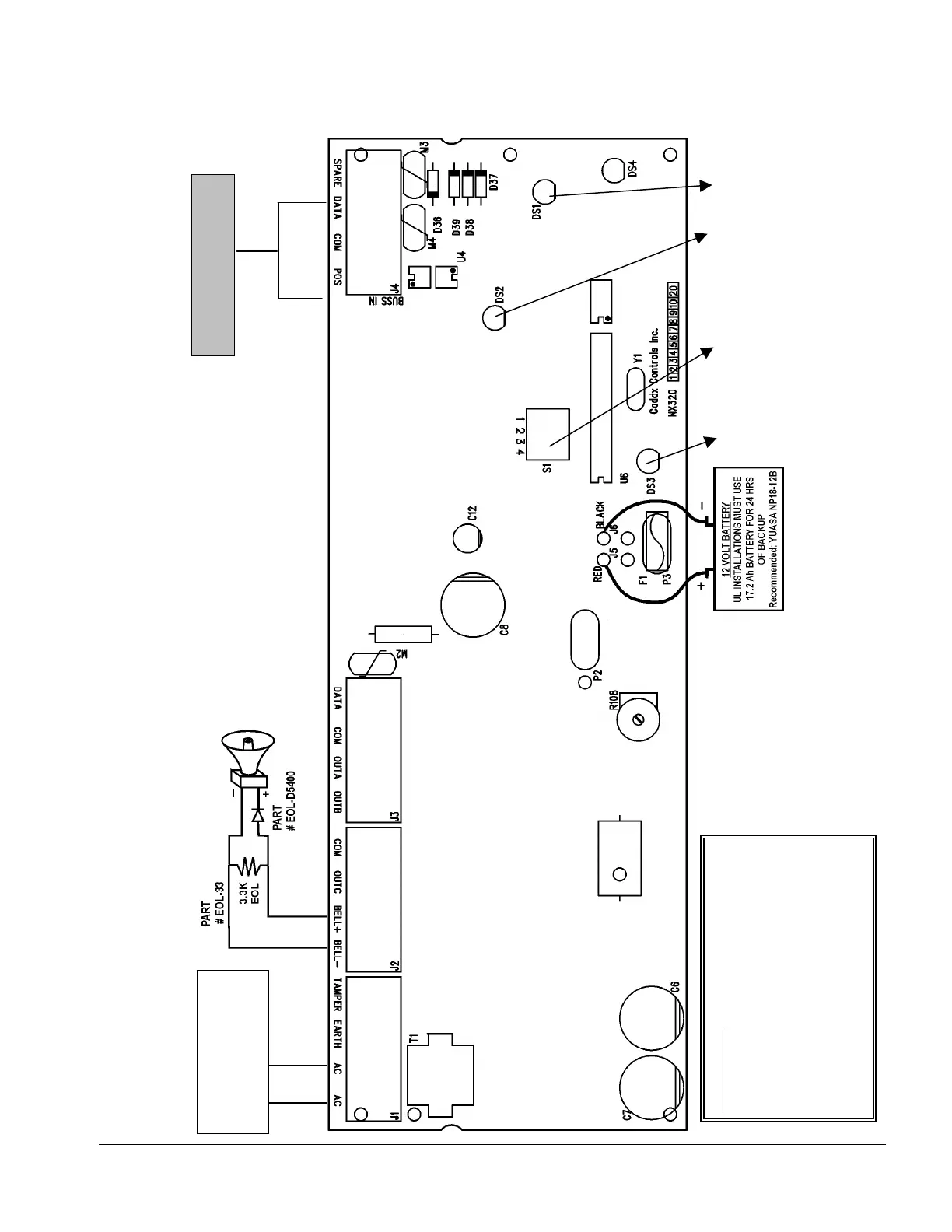
VIII. LAYOUT
BATTERY CAPACITY FOR
EMERGENCY STANDBY
AT LEAST 24 HOURS.
CONTROL PANEL DRAWS
50MA STANDBY POWER.
LED 1 LED 2
DIP
SWITCHES
LED 3
THE BELL OUTPUT IS VOLTAGE ONLY. IT IS PULSED
(TEMPORAL) DURING A FIRE ALARM AND STEADY
DURING A BURGLAR ALARM. IF THE BELL IS A
COMMERCIAL FIRE BELL, THE DIODE (EOL-D5400) IS
NOT NEEDED.
BELL CIRCUIT
CURRENT LIMITED TO
2.5 AMP MAXIMUM
CONNECT TO
CONTROL PANEL
Recommended:
Basler Model BE30614001
120VAC 60Hz
16.5VAC 50VA Class II
UL Installations: The Class 2, Class 3, and power
limited fire alarm circuits must be installed using
FPL, FPLP, FPLR, CL3, CL3R, or CL3P, or
substitute cable permitted by National Electrical
Code ANSI/NFPA70 and the Class 2, Class 3 and
power-limited fire alarm circuit conductors
extending beyond the cable jacket must be
separated a minimum of ¼ inch or by non
conductive tubing or non-conductive barrier from
all other conductors.

 Loading...