NX-320E Power Supply 5
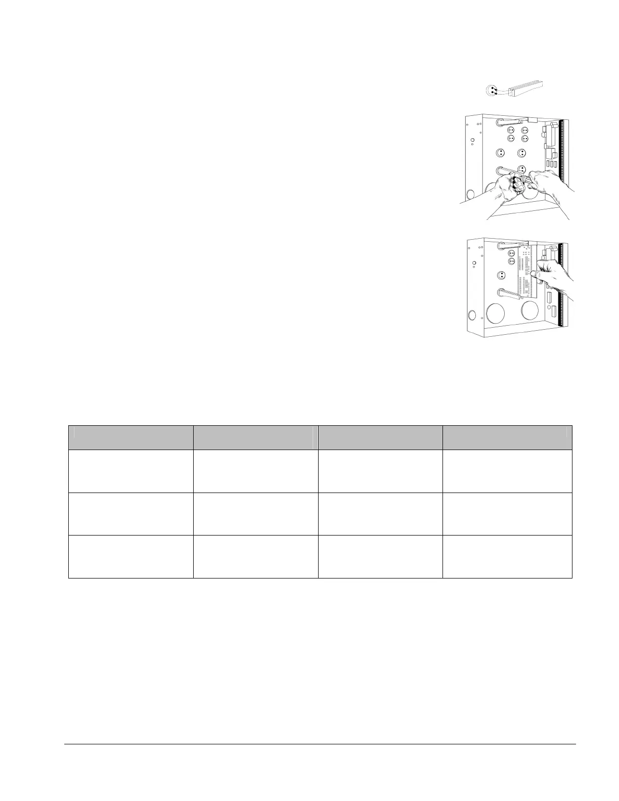
IV. ENCLOSURE DIAGRAM
Inside the can, several 2-holed insertion points have been constructed. This allows for
either vertical or horizontal placement of the modules. Notice that the insertion
points have two sizes of holes -- a larger hole and a smaller hole.
Diagram 1: The black plastic PCB guides are grooved on one edge where the PC
Board will be seated. The end with the half-moon protrusion fits into the larger hole.
The smaller hole is for the screw.
Diagram 2: Place the first black plastic PCB guide in the top insertion point, grooved
edge downward. The half-moon protrusion will be in the large hole. It does not
require force. Insert one of the provided screws into the smaller hole (from inside the
can) to secure it in place. A screwdriver should reach through the notch that runs the
length of the guide to tighten the screw. The second PCB guide should be
positioned opposite of the first (grooved edge up) and placed in the lower insertion
point, using the same procedures described above. Once mounted, screw it in
securely.
Diagram 3: The PC board should slide freely in the grooves of both guides.
V. BATTERY CALCULATION TABLE
STANDBY TIME TOTAL AUXILIARY
CURRENT
STANDBY BATTERY
CAPACITY
ALARM CURRENT
24 hours
1.9 Amps 51 AH 600 mA
1.25 Amps 34 AH 1 Amp
600 mA 17 AH 1 Amp
48 hours
900 mA 51 AH 1 Amp
600 mA 34 AH 1 Amp
300 mA 17 AH 1 Amp
72 hours
600 mA 51 AH 1 Amp
400 mA 34 AH 1 Amp
200 mA 17 AH 1 Amp

 Loading...