www.gemu-group.com 37 / 46 GEMÜ 550
10.6 Installation with threaded sockets
Fig.6: Threaded socket
NOTICE
Thread sealant
▶ The thread sealant is not included in the scope of deliv-
ery.
● Only use appropriate thread sealant.
1. Keep thread sealant ready.
2. Carry out preparations for installation (see chapter "Pre-
paring for installation").
3. Screw the threaded connections into the pipe in accord-
ance with valid standards.
4. Screw the body of the product onto the piping using ap-
propriate thread sealant.
5. Re-attach or reactivate all safety and protective devices.
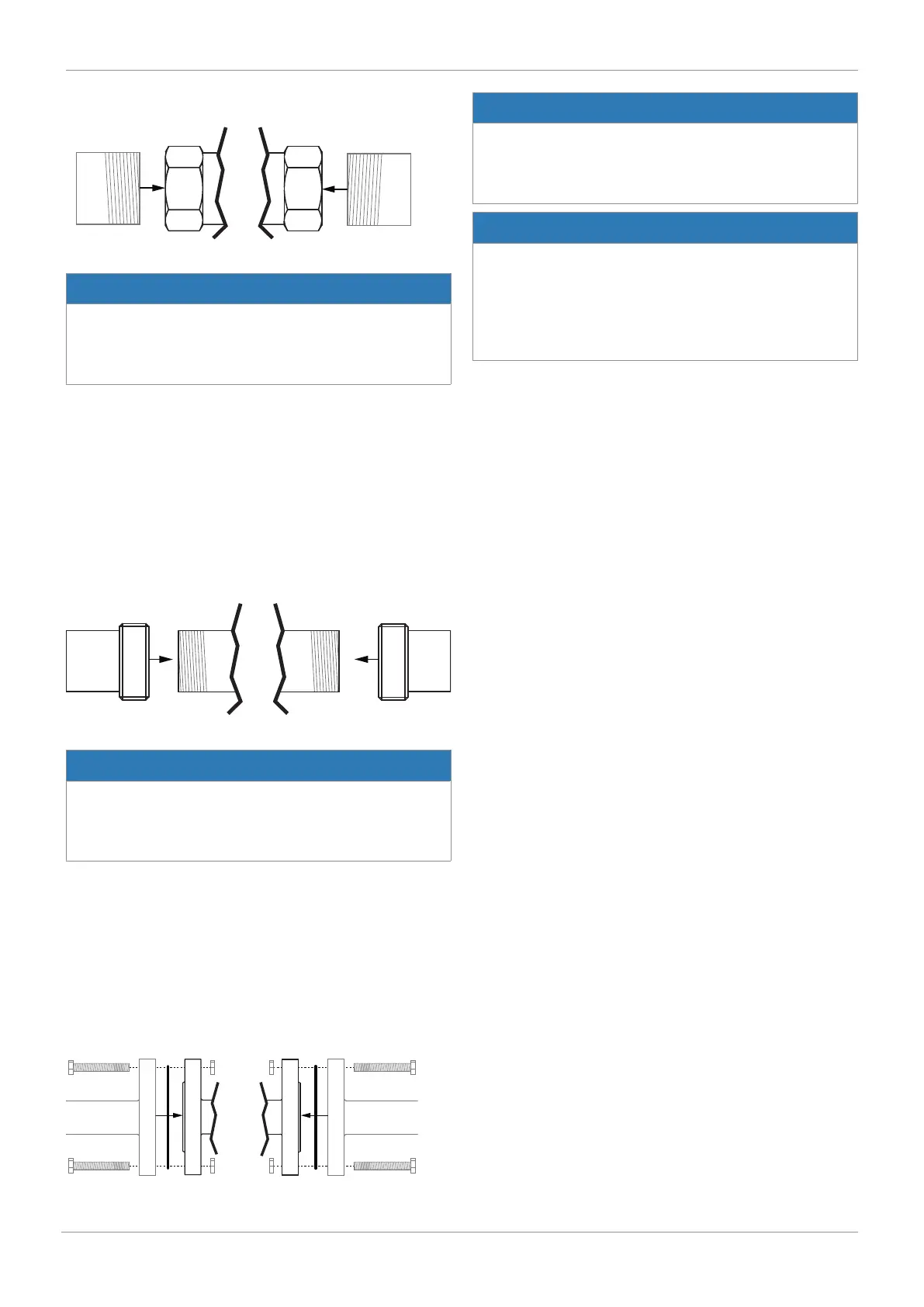
10.7 Installation with threaded spigots
Fig.7: Threaded spigots
NOTICE
Thread sealant
▶ The thread sealant is not included in the scope of deliv-
ery.
● Only use appropriate thread sealant.
1. Keep thread sealant ready.
2. Carry out preparations for installation (see chapter "Pre-
paring for installation").
3. Screw the pipe into the threaded connection of the valve
body in accordance with valid standards.
ð Use appropriate thread sealant.
4. Re-attach or reactivate all safety and protective devices.
10.8 Installation with flanged connection
Fig.8: Flanged connection
NOTICE
Sealing material
▶ The sealing material is not included in the scope of deliv-
ery.
● Only use appropriate sealing material.
NOTICE
Connector elements
▶ The connector elements are not included in the scope of
delivery.
● Only use connector elements made of approved materi-
als.
● Observe permissible tightening torque of the bolts.
1. Keep sealing material ready.
2. Carry out preparations for installation (see chapter "Pre-
paring for installation").
3. Ensure clean, undamaged sealing surfaces on the connec-
tion flanges.
4. Align flanges carefully before installing them.
5. Clamp the product centrally between the piping with
flanges.
6. Centre the gaskets.
7. Connect the valve flange and the piping flange using ap-
propriate sealing materials and matching bolting.
8. Use all flange holes.
9. Tighten the bolts diagonally.
10. Re-attach or reactivate all safety and protective devices.
10 Installation in piping
 Loading...


