76
Main
Main
udio door entry system with a.c. lock release and
A
additional TF-104 transformer..
75
Main
Next floor
BUS
BUS
HZ
HZ
HZ
HZ
T-7720
T-7720
BUS
HZ HZ
T-7720
BUS
HZS+ HZS-
T-7722VD
PA PB
BUS
HZS+ HZS-
T-7822VD
PA PB
BUS F.Ligne
( )
*
BUS
HZS+ HZS-
T-7722VD
PA PB
JP3
Main
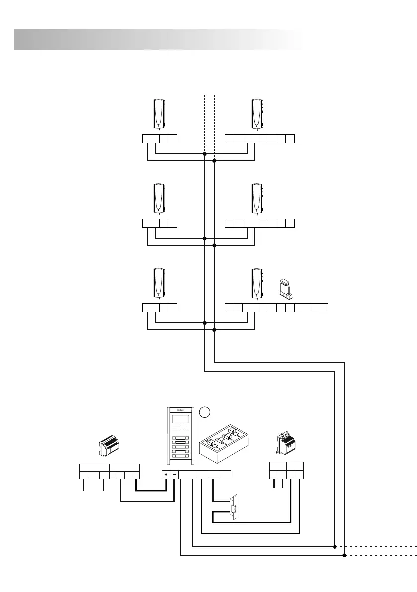
INSTALLATION DIAGRAMS
The installation diagram shows the wiring of an audio door entry system with one or several door
panels to enter into the building.
If the system has one door panel only, do not take into account the connection towards others.
If the system has more than one door panel, wire the second panel as shown on the diagram.
In case of more than two door panels, wire them as the second panel.
REMEMBER:
The maximum number of door panel in parallel without using converters is three.
.
.
.
Maximum distance between door panels: 50m.
Maximum distance between the remote door panel and furthest telephone: 100m.
.
.
Maximum length of all the bus wiring in the installation: 600m.
Sections chart
1,00mm² 1,50mm²
1,50mm²
Terminal
SECTIONS CHART
100m. 50m. 50m.
Panel - Telephone
Panel - Panel
F.A. - Panel - CV
+, -, CV1, CV2, ~,~
For higher distances, consult our Technical Assistance Service.
BUS
= Master.
= Slave.
M
S
BUS
CV1
+12
CV2
SEC
PRI
+
-
230110 0
FA-PLUS/C
ver. 938072
-
+
PRI
~~ ~~
SEC
TF-104
2Plus Nexa Door Panel
M
BUS
CV1
+12
CV2
SEC
PRI
+
-
230110 0
FA-PLUS/C
ver. 938072
-
+
PRI
~~ ~~
SEC
TF-104
2Plus Nexa Door Panel
S
( )
*
IMPORTANT: Do not insert the resistor with a 2Plus system.
 Loading...