STARTING RECOMMENDATIONS
54
O
O
O
O
Install or modify the equipment without the power connected.
O The installation and handling of these equipments must be performed by authorised personnel.
O The entire installation must be at least 40 cm. away from any other installation.
Do not use excessive force when tightening the screws of the power supply connector.
Before connecting the equipment, check the connections among the door pannel, telephones and the
power connection. Do always follow the enclosed information.
When starting the equipment for the first time, or after a modification, the system will remain inactive for
45 seconds because of the starting time.
.
.
.
.
.
O
O
O
O
O
O
O
O
O
O
O
w
w
w
O
w
Audio door entry system with simplified installation (2-wire bus withouth polarity).
Up to 3 access door pannels being not necessary the use of switching units.
(Up to 2 access door pannels if there is a digital converter CD-2PLUS in the building or backbone).
Up to 120 telephones per instalation without using converters.
Up to 120 apartments with door pannels with push buttons and 120 apartments with coded panel (being
necessary the use of digital converter CD-2PLUS).
Acoustic busy channel and call acknowledgement signals.
Maximum distance between door panels: 50m.
Maximum distance between the remote door pannel and furthest telephone: 100m.
Timed door opening for 3 seconds.
a.c. or d.c. lock release operated by relay.
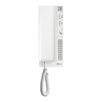
In T-7720 telephones:
Total private conversations.
Up to 1 additional telephone in every apartment.
Input for external door bell push button.
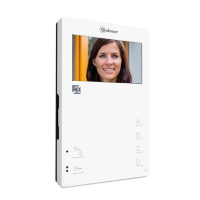
In T7722VD and T7822VD telephones have, besides the previous features:
Auxiliary push button with 2 possible functions:
e Relay activation SAR-2PLUS.
e Voltage-free contact (I máx: 40mA).
w Up to 2 additional telephones in every apartment (only with T-7822VD).
w Call volume regulation with three positions: maximum, medium and disconnection.
w Different call tones which identify the call procedure (main or secondary door panel or a call from the
landing).
w Call repeater S-45 output.
O It allows to install a porter´s exchange (being necessary the use of digital converter CD-2PLUS).
.
.
.
.
.
.
.
.
.
.
.
.
.
.
.
.
.
.
.
.
.
.
.
Maximum length of all the bus wiring in the installation: 600m.
SYSTEM CHARACTERISTICS
INTRODUCTION
INDEX
53
First of all we would like to thank and congratulate you for the purchase of this product manufactured by
Golmar.
The commitment to reach the satisfaction of our customers is stated through the ISO-9001 Certification
and for the manufacturing of products like this one.
Its advanced technology and exacting quality control will do that customers and users enjoy with the
legion of features this system offers. To obtain the maximum profit of these features and a properly wired
installation, we kindly recommend you to expend a few minutes of your time to read this manual.
.
.
Introduction...........................................53
Index.....................................................53
Starting recommendations.......................53
Safety precautions...................................54
System characteristics..............................54
System operation ....................................55
Door panel description............................56
Modules description....................................
Sound module EL620/2Plus.....................57
Push buttons module EL610D...................58
Door panel ................................................
Embedding box positioning ...................59
Embedding box installation ..............59-60
Assembly electronic modules .................60
Hold the frame.....................................61
Push buttons connection...................61-62
Push button coding...............................62
Sound module configuration..................63
Self-testing Leds ...................................63
Final adjustments .................................64
Close the frame....................................64
Placing the nameplate labels..................64
Door panel assembly ............................65
Close the door panel.............................65
Power supply installation..........................66
Lock release installation...........................66
Telephones T-7720, T-7722VD & T-7822VD....
Description..........................................67
Function push button.............................67
JP3 jumper config. (only T-7822VD)........68
Fixing the telephone..............................68
Programming.......................................69
Optional connections..................................
Door bell push button............................70
External lock release activation...............70
Additional telephone or call repeater.......70
Auxiliary devices activation ....................71
Garage door release ............................72
Wiring diagrams.........................................
With d.c lock release........................73-74
With a.c lock release / TF104............75-76
Troubleshooting hints ..............................77
Notes....................................................78
Compliance...........................................79
O
O
O
O
w
w
w
w
w
O
w
w
w
O
Install or modify the equipment without the power connected.
The installation and handling of these equipments must be performed by authorised personnel.
The entire installation must be at least 40 cm. away from any other installation.
With power supply:
w Do not use excessive force when tightening the connector screws.
Install the power supply in a dry and protected place without risk of drip or water projections.
Avoid to place it near to heating sources, in dusty locations or smoky enviroments.
Do not block ventilation holes of the unit so that air can circulate freely.
To avoid damage, the power supply has to be firmly fixed.
To avoid an electrical shock, neither remove the protection cover nor handle the connected wire in
the terminals.
With telephones, SAR-12/24 relay and S-45 call repeater:
Do not use excessive force when tightening the connector screws.
Install the power supply in a dry and protected place without risk of drip or water projections.
Avoid to place it near to heating sources, in dusty locations or smoky enviroments.
w Do not block ventilation holes of the equipments so that air can circulate freely.
Do always follow the enclosed information.
.
.
.
.
.
.
.
.
.
.
.
.
.
.
.
SAFETY PRECAUTIONS
 Loading...