60
59
ssembly the electronic modules.
A
Insert the sound module in the top part of the module frame.
Align the tabs on the sound module in their respective housings of the module frame and
later exercise a light pressure until correct placement.
Sound module
EL620/2Plus
Push buttons electronic
module EL610D
Frame
If there is push buttons module repeat the above process, locating under the sound module,
as shown in the drawing.
Frame
lace the embedding box.
P
Pass the wiring through the hole made in the bottom part of the
embedding box. Level and flush the embedding box. Once
the embedding box is placed, remove the protective labels
from the attaching door panel holes.
90CS
CEA90C
99
143
40
Door panel
Model
An
Al
P
90C
CEV90C
99
250
56
90
CEV90
99 mm.
328 mm.
56 mm.
DOOR PANEL INSTALLATION
DOOR PANEL INSTALLATION
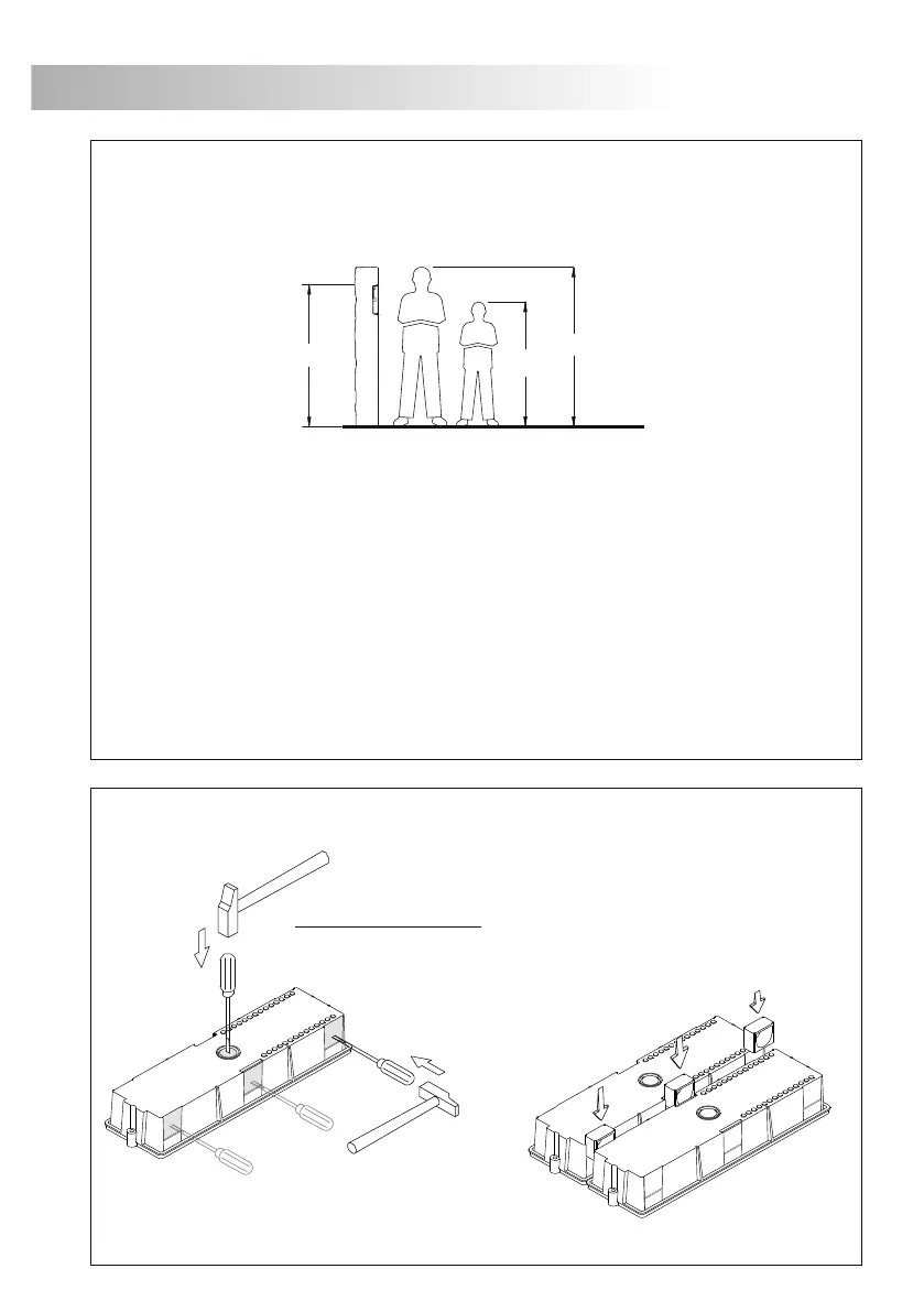
mbedding box positioning.
E
The upper part of the door panel should be placed at 1,65m. height roughly. The hole dimensions
will depend on the type of door panel.
The door panel has been designed to be placed under most of the environmental conditions.
However it's recommended to take additional cautions like rainproof covers.
reparing the cables entry.
P
Break the bottom flange to pass the cables through. In case of door panels
with more than one embedding box, break the side flanges and
attach the embedding boxes using UC junctions.
1650
1850
1450
 Loading...