43
06 Electrical ConnectionUser Manual V1.1-2022-12-20
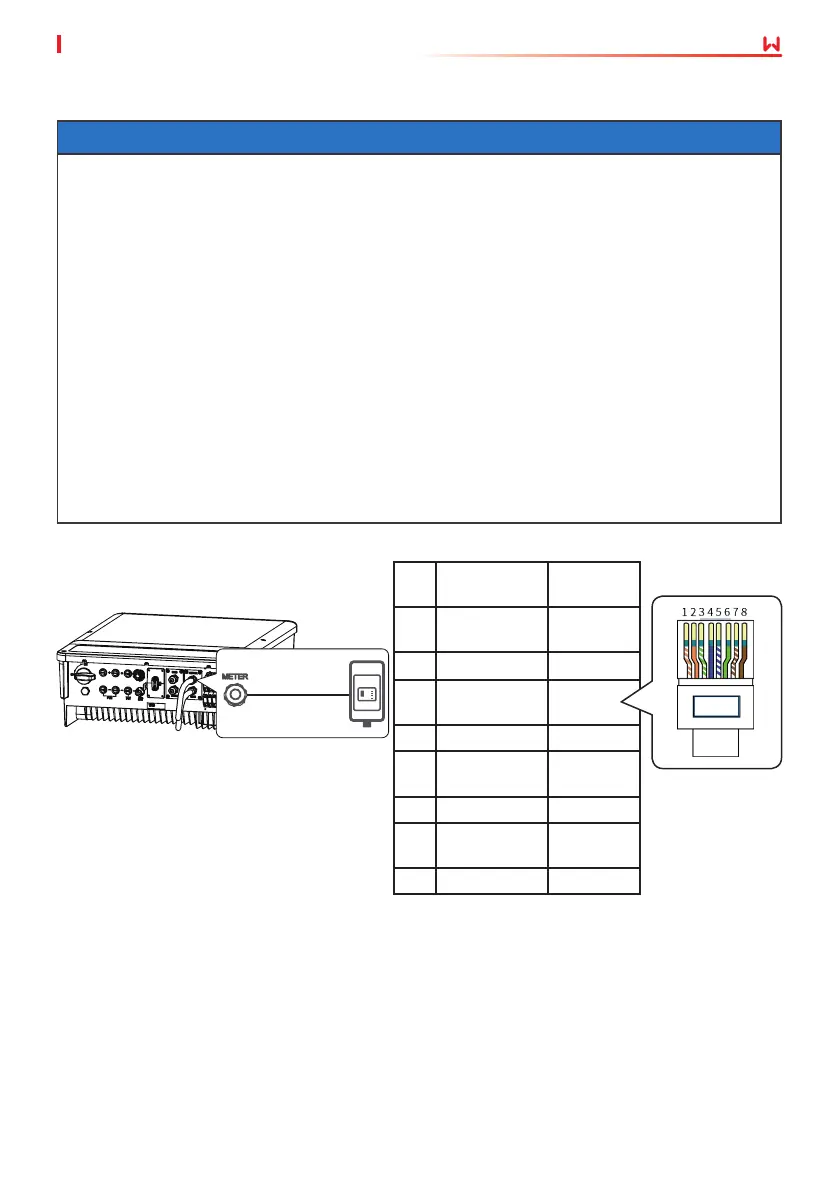
No. Color
Smart
meter
1
Orange and
White
NC
2 Orange
NC
3
Green and
White
485_B1
4 Blue NC
5
Blue and
White
NC
6 Green 485_A1
7
Brown and
White
485_B1
8 Brown 485_A1
NOTICE
• The smart meter and CT have been preset parameters before delivered with the inverter.
Do not modify the relevant parameters.
• Each smart meter needs to be connected to one inverter independently. Do not connect
one smart meter to multiple inverters.
• Conrm the following items for a proper use of the smart meter and CT:
1. Ensure that CT connects with the corresponding phase line: CT1 is connected to L1; CT2
is connected to L2; and CT3 is connected to L3.
2. Connect CT according to the pointing direction of the smart meter. It will display CT
reverse fault on the inverter if it is the opposite direction.
• The CT cable is 3m or 5m long as a default.
• The communication cable connecting the inverter and the smart meter cannot be longer
than 100m. RJ45 connector with the following denition can be connected for BMS
communication:
6.7.2 Connecting the Meter Communication Cable
To Smart Meter
 Loading...