03 Product Introduction
User Manual V1.3-2023-01-31
6
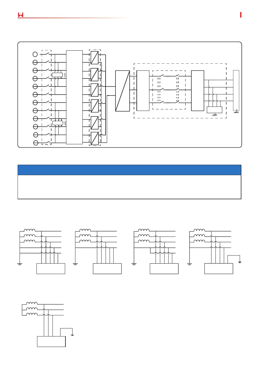
The grid structures supported by SMT is TN-S, TN-C,TN-C-S, TT, IT, as shown in the gure below:
Inverter
Inverter
Inverter
Inverter Inverter
3.3 Supported Grid Types
NOTICE
• For the TT grid structure, the eective value of the voltage between the neutral wire and
the ground wire must be less than 20V.
• For the grid type with neutral wire, the N to ground voltage must be less than 10V.
The circuit diagram of GW60KS-MT, GW60KS-MT-EU and GW35KLS-MT is as follows.
Transformer Transformer Transformer Transformer
L1
L2
L3
PEN
PE
L1
L2
L3
N
PE
PE
L1
L2
L3
N
PE
L1
L2
L3
N
PE
PE
PE
L1
L2
L3
Transformer
TN-S TN-C TN-C-S TT
IT
MPPT 1+
MPPT 1-
MPPT 2+
MPPT 2-
MPPT 3+
MPPT 3-
MPPT 4+
MPPT 4-
MPPT 5+
MPPT 5-
SWITCH
DC SPD
DC SPD
DC
EMC
Filter
BOOST
DC
DC
DC
DC
DC
DC
DC
DC
DC
DC
BUS
INV
DC
AC
OUT FILTER
AC RELAY
AC
EMC
Filter
AC
Filter
AS SPD
L1
L2
L3
N
PE
MPPT 6+
MPPT 6-
DC
DC
 Loading...