User Manual V1.3-2023-01-31
03 Product Introduction
7
3.4 Appearance
3.4.1 Parts
GW12KLV-MT, GW15KLV-MT, GW20KLV-
MT, GW25K-MT, GW29.9K-MT, GW30K-MT,
GW36K-MT
GW30KLS-MT, GW35KLS-MT, GW50KS-
MT, GW50KS-MT-EU, GW60KS-MT and
GW60KS-MT-EU
[1] GW12KLV-MT, GW15KLV-MT, GW20KLV-MT, GW25K-MT, GW29.9K-MT, GW30K-MT, GW36K-MT:
Optional.
GW30KLS-MT, GW35KLS-MT, GW50KS-MT, GW60KS-MT, GW50KS-MT-EU and GW60KS-MT-EU:
Standard.
[2] GW30KLS-MT, GW50KS-MT and GW50KS-MT-EU: MTTP x 5.
GW35KLS-MT, GW60KS-MT and GW60KS-MT-EU: MTTP x 6.
[3] GW50KS-MT-EU and GW60KS-MT-EU: N/A.
[4] Only for GW50KS-MT-EU and GW60KS-MT-EU.
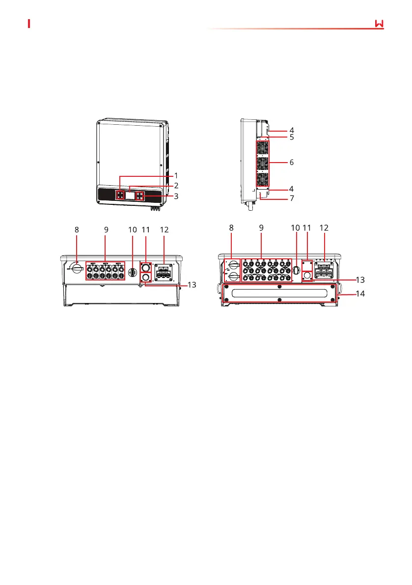
1. Indicator 2. LCD (optional) 3. Button (optional)
4. Mounting Plate 5. Handle
[1]
6. Fan
7. PE Terminal 8. DC Switch 9.
PV Input
Terminal
[2]
10.
Communication Module
Port (Wi-Fi/LAN Kit or
WiFi or 4G or GPRS)
11.
COM Port (USB or DRED
or Remote Shutdown or
Emergency Power O)
[3]
12. AC Output Port
13. RS485 COM Port 14. Capacitor Box
[4]
The colors of the inverter are designed as red, white, and so on. The graphic on the cover is for
reference only.
 Loading...