5 Pipe Connections
16
Pipe Connections
5.1 Water Connections
Water connections may be from the
rear, left or right hand side. If using low
level side exit flue, connections must be
on the opposite side to the flue.
Flow and return connections - All
models are supplied with a push-fit
elbow connection for the heating flow
and return - 22 mm (Vortex Pro Combi
21e and 26e) or 28 mm (Vortex Pro
Combi 36e).
Hot water connections - All models are
supplied with push-fit elbow
connections for the cold water mains
inlet pipe and hot water outlet pipe.
These are 15mm for the Vortex Pro
Combi 21e and 26e, and 22mm for the
Vortex Pro Combi 36e.
5.2 Making the Water
Connections
Flow and return pipework can be routed
to either side of the boiler, dependant on
the flue system used, from the push-fit
elbows (supplied) on the flow and return
connection. Refer to Figure 5-1.
Holes are provided in the rear of the
casing side panels to allow the
condensate pipe to be run through the
back of the boiler. It will be necessary to
remove the back panel from the boiler
casing to fit this pipework, and to refit
the panel before placing the boiler in its
final position. See Figure 6-3.
If access will be restricted, make any
connections to the boiler before placing
it in its final position.
If using a balanced flue system - Install
the balanced flue system before
connecting the heating system
pipework to the boiler.
All Models
A 15 mm discharge pipe must be
connected to the safety valve outlet
connection. The pipework between the
safety valve and the boiler must be
unrestricted, that is, no valves. The
discharge pipe should be run to the
outside of the building and terminate so
that it cannot cause injury to persons or
property.
A drain tap is provided at the bottom on
the front of the boiler (and also on the
hot water store on the Vortex Pro
Combi e).
All pipes to be fitted into the push-fit
connectors provided should be cut
using a pipe slicer or pipe cutter - to
leave the pipe ends with a slight
radius and free from any burrs or
sharp edges.
Pipes to be used with these fittings
should not be cut square using a
hacksaw.
!
CAUTION
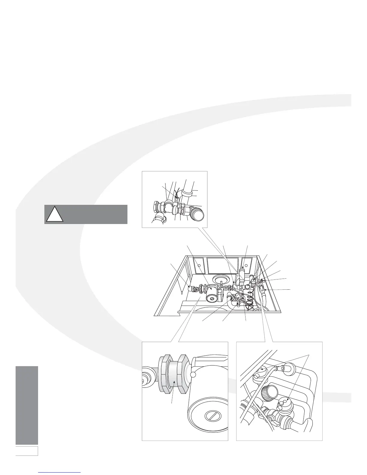
Figure 5-1: Vortex Pro Combi e pipe positions
Heating flow
connection
Heating circulating
pump
Heating
return
Flow switch
Cold water inlet
isolating valve
Cold water inlet
Automatic air vent
Safety valve
Pressure
switch
Manual
air vent
Primary return
isolating valve
Non return
valve
Automatic
air vents
Boiler flow
sensor and
overheat
thermostat
bulb
Safety valve
outlet
 Loading...


