Commissioning
43
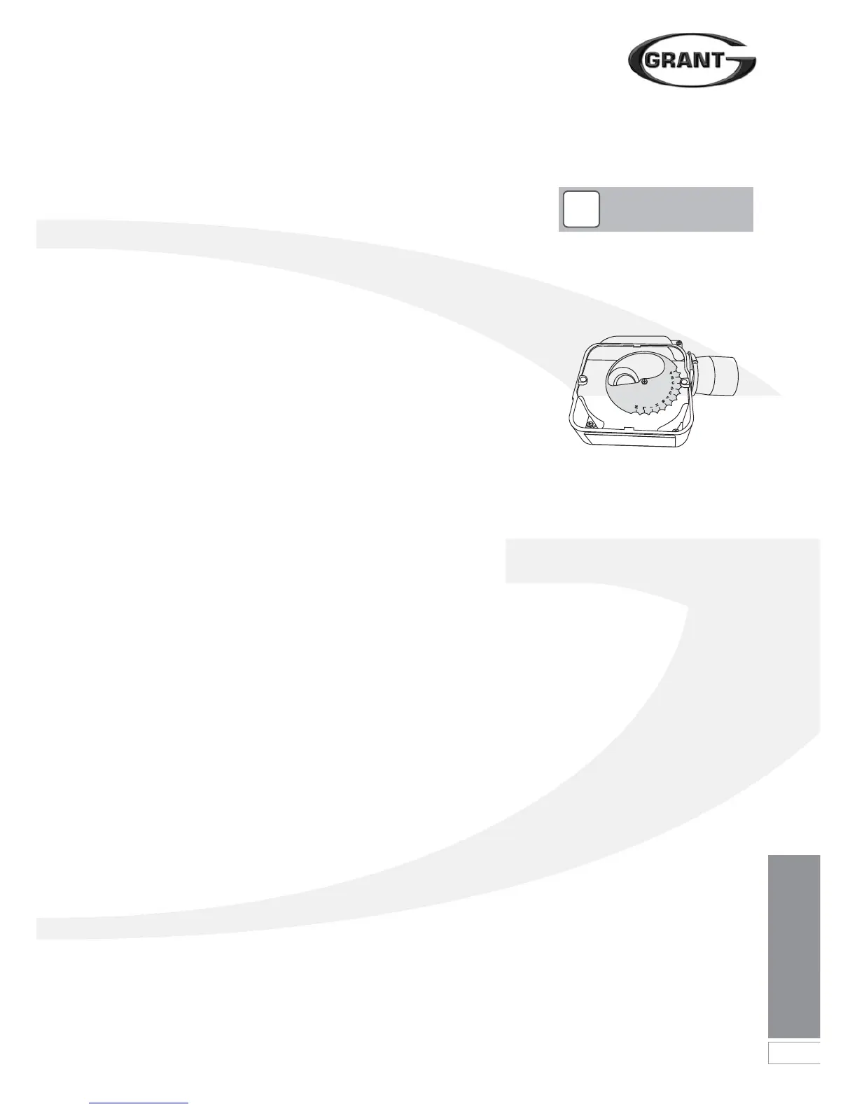
10.6 Air Adjuster Disc – Combi
21 only
The Riello RDB 2.2 burner fitted to this
boiler incorporates a secondary air
adjustment shutter located within the air
inlet housing.
It is essential that this internal shutter
disc be correctly set to position ‘C’.
Refer to Figure 10-4.
To access the air adjuster disc:
1. Ensure the boiler is isolated from the
electrical supply.
2. Remove the burner from the boiler.
3. Undo the four screws and remove
the air inlet cover from the side of
the burner.
4. The secondary air shutter disc is
factory set in position ‘C’ – i.e. with
the cut-out marked C located
against the die-cast boss on the fan
housing. See Figure 10-4.
5. If not set to position ‘C’: remove the
screw from the centre of the air
shutter disc, and re-position it such
that the cut-out ‘C’ is located
against the cast boss on the fan
housing. Replace the screw in the
centre of the air shutter disc and
tighten.
6. Re-fit the air inlet cover to the side
of the burner and reassemble in
reverse order.
10.7 Information for the User
The User must be advised (and
demonstrated if necessary) of the
following important points:-
• How to start and switch off the
boiler and how to operate the
system controls.
• The precautions necessary to
prevent damage to the central
heating system and to the building,
in the event of the boiler not being in
operation during frost conditions.
• The importance of servicing the
boiler to ensure safe and efficient
operation. This should normally be
required only once a year.
• The type of fuel used.
• That any servicing or replacement of
parts must only be carried out by a
suitably qualified engineer.
• Ensure that the boiler controls and
room thermostat (if fitted) are set to
the User's requirements.
• Tell the User the system pressure
and show them the position of the
safety valve discharge pipe.
• Show the User how to reset the
overheat thermostat and how to
restart the boiler if it goes to 'Lock-
out'.
Leave this Instruction manual with
the User.
Ensure the User information pack has
been given to the Householder.
!
NOTE
Figure 10-4: Burner air adjuster disc
(shown set to position C)
 Loading...


