Flue System and
Air Supply
35
9.3 Connecting a
Conventional Flue
1. Unscrew and remove top casing
panel.
2. Push out the pre-cut blanking panel.
If the Grant ‘Orange’ flue system is
being used, follow the instructions
supplied with the flue kit.
If the Grant ‘Green’ system (100mm
rigid twin wall flue) is to be fitted to the
boiler then the Grant CF adaptor kit
(Ref. CFA15/70) must be used - refer to
Section 1.2.
To fit the adaptor kit, proceed as
follows:
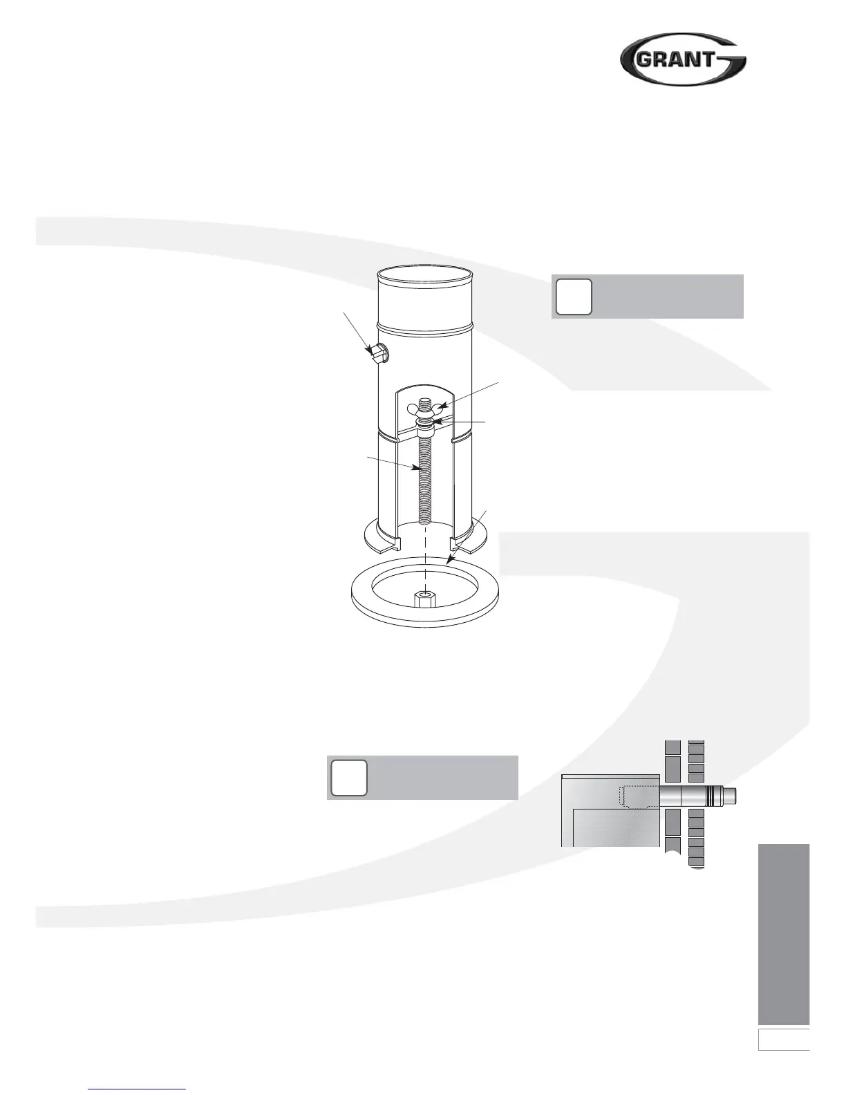
1. Fully screw the length of threaded
studding (provided in the kit) into the
nut located in the centre of the
boiler flue outlet.
2. Fit the boiler connector (from the CF
adaptor kit) over the threaded
studding.
3. Position flange on to the neoprene
gasket around the boiler flue outlet,
ensuring that small spigot on the
base of the connector is located in
the hole in the centre of the
neoprene gasket and that the end of
the studding passes through the
hole in the base of the spacer
bracket.
4. Fit the washer and wing nut
provided onto end of threaded
studding and secure the connector
in position by tightening down on the
wing nut - as shown in Figure 9-5.
5. Re-fit the top casing panel to the
boiler - fitting it over the boiler
connector.
6. Fit the flue adaptor (from the adaptor
kit) into the boiler connector.
Figure 9-5: Boiler flue connector
9.4 Balanced Flue Systems
Apart from a conventional flue, several
balanced flue options are available for
use with the Grant Vortex Pro Combi e
boilers. All are suitable for use with
Class C2 kerosene.
Lubricate the seal on the flue
connector using the lubricant
provided before attempting to fit the
flue connector.
7. Fit the first section of flue into the
flue adaptor and secure using the
clamp band provided.
8. Assemble the remainder of the flue
system as required, lubricating the
seal on each component before
fitting.
!
NOTE
!
NOTE
None of the flue sections in the
following system can be cut.
Low Level Horizontal Balanced Flue
(Yellow system)
The Grant ‘Yellow’ system low level
balanced flue is available in either Short
(for single thickness brick walls) and
Standard kits.
Extensions are available which extend
the flue by 225mm, 450mm or 675mm.
90° and 45° elbows are also available.
The maximum flue length - from the
centre of the boiler flue outlet to the
outer face of the wall - is 4 metres (with
or without elbows included). No more
than 2 x 45° or 1 x 90° elbow should be
fitted per system.
The ‘Yellow’ system low level balanced
flue is supplied with a stainless steel
guard. This must be fitted in all
circumstances to prevent objects from
entering the flue outlet.
The guard must be fitted centrally over
the flue terminal and securely fixed to
the wall.
Figure 9-6: Low level balanced flue
‘Yellow’ system)
Test point
screw
Threaded
studding
Wing nut
Washer
Neoprene
gasket
 Loading...


