123 456 789 101112 13141516 1718 212219 20 23 24 27 2825 26
ENL
N
NL 3
NLON
412
N COM ON
3154 2
LN
Grant Plug-in (panel mounted)
Programmer
Grant Ref. EPKIT
Room Thermostat
e.g. Danfoss Randall
RMT230
Frost Thermostat
(if required)
e.g. Danfoss Randall
RET230F
HTG
OFF
CH
ON
HTG
ON
EL
Mains
Ext. Frost Stat
Ext. Frost Stat
Room Stat
Room Stat
Timer Neutral
Timer Live
DHW Timed On
CH Timed On
230V 5A Fused
Supply
8 Electrical
28
Electrical
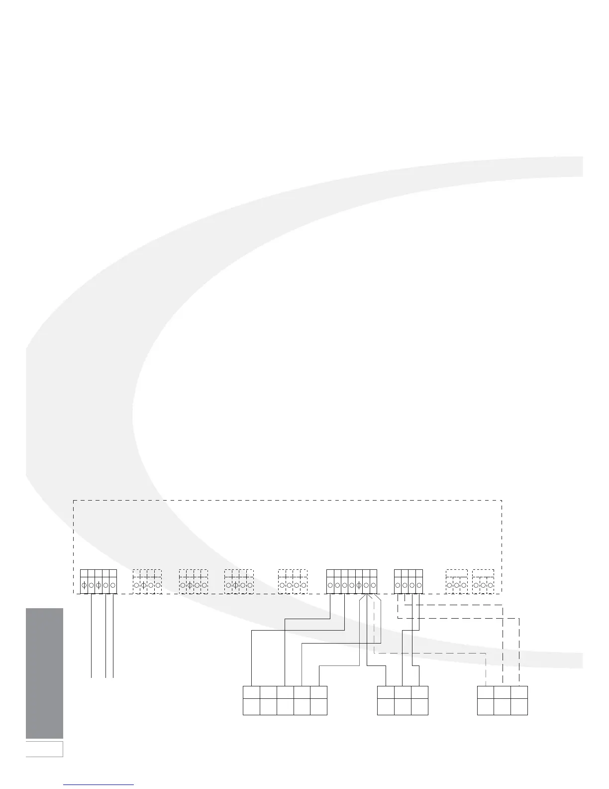
Figure 8-7: Connections for the Grant Plug-In 2-channel Programmer (EPKIT) and room thermostat
8.3 Connecting the Controls -
Heating and Hot Water
If control of both heating and hot water
operation of the boiler is required, it is
recommended to use one of the
following options:
• A Grant ‘plug-in’ two channel
programmer (Ref. EPKIT) and room
thermostat.
• A Grant ‘wireless’ RF two-channel
programmable room thermostat
(Ref. RFTKIT).
• A Grant two-channel remote
programmer (Ref. ESKIT) and room
thermostat.
Fitting and connection of a Grant
‘plug-in’ electronic programmer
(EPKIT) and room thermostat
Pass a 3-core cable (or 3-core and
earth if the room thermostat to be used
has an earth connection) through the
cable clamp on the control panel.
Remove the Orange room thermostat
link wire from terminals 25 & 26 on the
connection block and connect the wires
from the room thermostat. Refer to
Figure 8-7 for further details.
Connect the room thermostat to the
terminal block in accordance with the
room thermostat manufacturer’s
instructions.
Fit and connect the ‘plug-in’
programmer as follows:
1. Remove front and top boiler casing
panels. Loosen (do not remove) the
four screws securing control panel
to the side panels
2. Hinge the panel forward to access
top and rear of control panel. Remove
the two screws and lift off the terminal
block cover from top of control panel.
3. Remove both the Red and Black
wire links from terminals 17 & 18
and 19 & 20 on control panel.
4. Carefully push through and remove
square pre-cut 'knockout' section in
the control panel front.
5. Connect four wires provided to
terminals of the electronic
programmer as shown below.
Note that the Yellow wire supplied
in the kit must not be used.
6. Feed the wires through hole in
control panel front and then up
through rectangular opening in
control panel top. Connect wires to
terminals on control panel as follows:
• Orange wire (from Terminal 3 on
programmer) to Terminal 17 on
PCB plug.
• Red wire (from Terminal 5 on
programmer) to Terminal 19 on
PCB plug.
• Blue wire (from Terminal 2 on
programmer) to Terminal 21 on
PCB plug.
• Brown wire (from Terminal 1 on
programmer) to Terminal 22 on
PCB plug.
Refer to Figure 8-7 for connection
diagram.
7. Locate the electronic programmer in
the square hole in control panel front
- with the terminals pointing to the
right. Secure by turning the two
screws (in upper right and lower left
corners) a quarter turn clockwise.
8. Re-fit terminal block cover on
control box and fasten with the two
screws previously removed.
9. Hinge the control panel back into
position on the two retaining
screws. Replace top casing panels.
10. Re-connect electrical supply and
check operation of the programmer
and room thermostat.
Refer to the Fitting and User
Instructions supplied with the
programmer for operating and
setting.
Leave the Programmer and Room
Thermostat Fitting & User
instructions with the user after
installation.
Red
Orange
Brown
Blue
Boiler Control Panel - PCB Connections
 Loading...


