24
Electrical
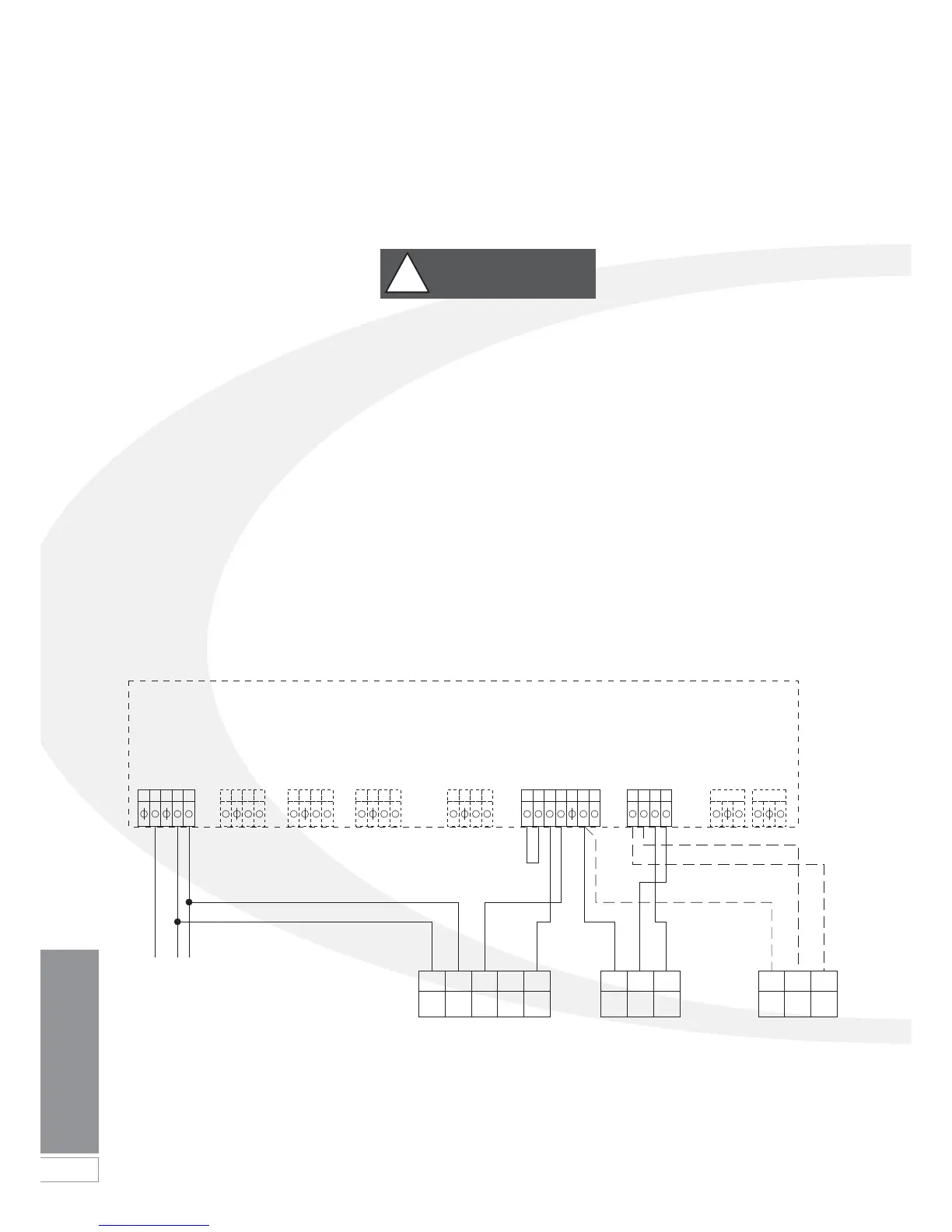
Figure 8-3: Connections for a remote timer and room thermostat
8.2 Connecting the Controls -
Heating Only
To control the central heating on/off
periods only (and not the domestic hot
water), it is recommended to use one of
the following options:
• A remote single channel timer and
room thermostat.
• A ‘plug-in’ Grant Mechanical 24-
hour timer (Ref. MTKIT) and room
thermostat.
• A ‘plug-in’ Grant Electronic 7-day
timer (Ref. ETKIT) and room
thermostat.
• A Grant programmable room
thermostat.
With any of these options the timer,
room thermostat or programmable
room thermostat should be sited at a
suitable and convenient location within
the property.
Connection of an External Remote
Timer and Room Thermostat
Pass a 3-core cable (or 3-core and
earth if the room thermostat to be used
has an earth connection) through the
cable clamp on the control panel.
Remove the Orange room thermostat
link wire from terminals 25 & 26 on the
connection block and connect the wires
from the room thermostat. Refer to
Figure 8-3 for further details.
Connect the room thermostat to the
terminal block in accordance with the
room thermostat manufacturer’s
instructions.
Pass a 4-core cable (or 4-core and
earth if the timer to be used has an
earth connection) through the cable
clamp on the control panel.
Remove the Black link wire from
terminals 19 & 20 on the connection
block. Connect the two switch wires
from the timer.
Connect the live, neutral (and earth if
required) from the timer to terminals 3, 2
& 1 respectively on the boiler terminal
block. Refer to Figure 8-3 for further
details.
Re-fit terminal block cover on control
box and fasten with the two screws
previously removed.
Hinge the control panel back into
position on the two retaining screws.
Replace top casing panels.
Re-connect electrical supply and check
operation of the timer and room
thermostat.
Refer to the Fitting and User Instructions
supplied with the timer for operating
and setting.
Leave the Timer and Room Thermostat
Fitting and User instructions with the
user after installation.
Any remote timer must be of a single
channel 230V type with voltage free
output contacts.
!
WARNING
123 456 789 101112 13141516 1718 212219 20 23 24 27 2825 26
ENL
N
NL 3
NLON
412
N COM ON
12NL 4
COM
Remote mounted
Time Switch
e.g. Danfoss Randall
TS715
Room Thermostat
e.g. Danfoss Randall
RMT230
Frost Thermostat
(if required)
e.g. Danfoss Randall
RET230F
HTG
OFF
HTG
ON
EL
Mains
Ext. Frost Stat
Red
Ext. Frost Stat
Room Stat
Room Stat
Timer Neutral
Timer Live
DHW Timed On
CH Timed On
230V 5A Fused
Supply
8 Electrical
Boiler Control Panel - PCB Connections
 Loading...


