Condensate
Disposal
19
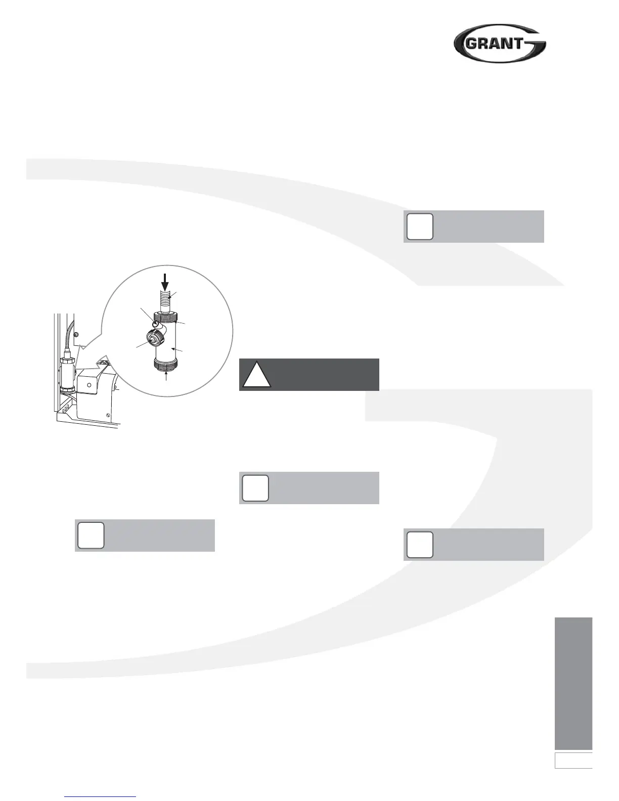
6.6 Condensate Trap
Grant Vortex PRO boilers are supplied
with a factory-fitted condensate trap to
provide the required 75mm water seal in
the condensate discharge pipe from the
boiler.
This trap incorporates a float (which will
create a seal when the trap is empty)
and an overflow warning outlet (fitted
with a plastic sealing cap).
See Figure 6-2.
6.9 External Condensate Trap
Fitting
To re-locate the factory-fitted trap
outside the boiler casing, use the
following procedure:
6.8 Inspection and Cleaning of
Trap
The trap must be checked at regular
intervals (e.g. on every annual service)
and cleaned as necessary to ensure
that it is clear and able to operate.
To inspect and clean the trap, perform
the following procedure:
1. Disconnect flexible condensate
hose from inlet connector.
2. Unscrew the inlet connection nut.
3. Remove the ‘top hat’ inlet
connector and nut from trap.
4. Disconnect the condensate disposal
pipe from the trap outlet.
5. Remove trap from bracket.
6. Remove float from trap - clean if
necessary.
7. Inspect inside of trap and clean as
necessary.
8. Re-assemble trap, re-fit to boiler
and re-connect flexible hose. Ensure
that hose is fully pushed onto the
‘top hat’ inlet connector.
With the trap fitted inside the boiler
casing, the sealing cap must be
fitted. If the trap is re-located outside
the boiler then the following applies:
• If connecting the condensate discharge
- either internally or externally - into a
waste system or soil stack - the sealing
cap must be fitted in the trap outlet.
• On external discharge systems to a
hopper, gully or soakaway, the
sealing cap should be removed from
the trap outlet.
• If there is any discharge of
condensate from the overflow
outlet, this could indicate a
blockage (possibly due to freezing).
Turn off the boiler and investigate
the cause. If necessary contact your
service engineer for assistance.
6.7 Condensate Disposal
Pipework
The condense trap outlet is at an angle
of 48° below the horizontal. This is to
automatically gives a 3° fall on any
‘horizontal’ runs of condense disposal
pipe. Refer to Figure 6-1 and see trap
outlet/pipe.
The outlet of the trap will accept
21.5mm OD to 23mm OD
Polypropylene overflow pipe for the
condensate discharge pipe.
This discharge pipe can exit through the
left side of the boiler through one of two
pre-cut ‘knock-outs’ in the lower part of
the left casing panel. Push out the
‘knock-out’ from the required hole
taking care not to distort the side panel.
Refer to Figure 2-1 for this on the Pro
Combi 21e or 26e, or Figure 2-2 for this
on the Pro Combi 36e.
The trap is factory-fitted inside the boiler
casing - mounted on the inside of the
left side panel - in an accessible position
to allow for routine maintenance.
A flexible hose connects the outlet of
the condensing heat exchanger to the
trap inlet. Ensure the straight connector
on the hose is fully pushed onto the ‘top
hat’ inlet connector of the trap.
Figure 6-2: Condensate trap
If required, this condensate trap may
be re-located outside the boiler
casing. Refer to procedure given in
‘external condensate trap’. This
procedure must be carried out
before the boiler is installed.
!
NOTE
The bottom bowl is sealed to the trap
body and cannot be removed.
!
NOTE
End cap is sealed to trap body. DO
NOT attempt to remove it for cleaning.
!
NOTE
Failure to regularly check and clean
the condensate trap may result in
damage to the boiler and will not be
covered by the Product Warranty.
!
NOTE
Condensate
drain pipe
from boiler
Unscrew
this cap for
maintenance
access
Overflow
warning
outlet
(with cap)
Condensate
trap
Condensate
outlet to
drain
End cap
Care should be taken when siting the
trap such that the overflow outlet is
readily visible and that any
condensate overflowing from the
outlet cannot cause either a hazard
to persons or damage to surrounding
property or equipment.
!
WARNING
 Loading...


