Flue System and
Air Supply
39
!
NOTE
!
NOTE
Dimension B given in Figure 9-13
includes an extra 10 mm over the
size of the terminal to provide
clearance for fitting.
Fitting instructions for the high level
balanced flue and vertical balanced
flue are supplied with the flue kits.
Adjustable Extensions
The adjustable extensions are
telescopic. The wall terminal section is
adjustable and is suitable for a wall
thickness of 215mm to 450mm.
Simply adjust to the required length
using a twisting motion. The outer pipes
must overlap by a minimum of 25mm.
9.6 High Level and Vertical
Balanced Flue
If the boiler is to be used with the high
level balanced flue (White system) make
the hole in the wall as shown in Figure
9-13.
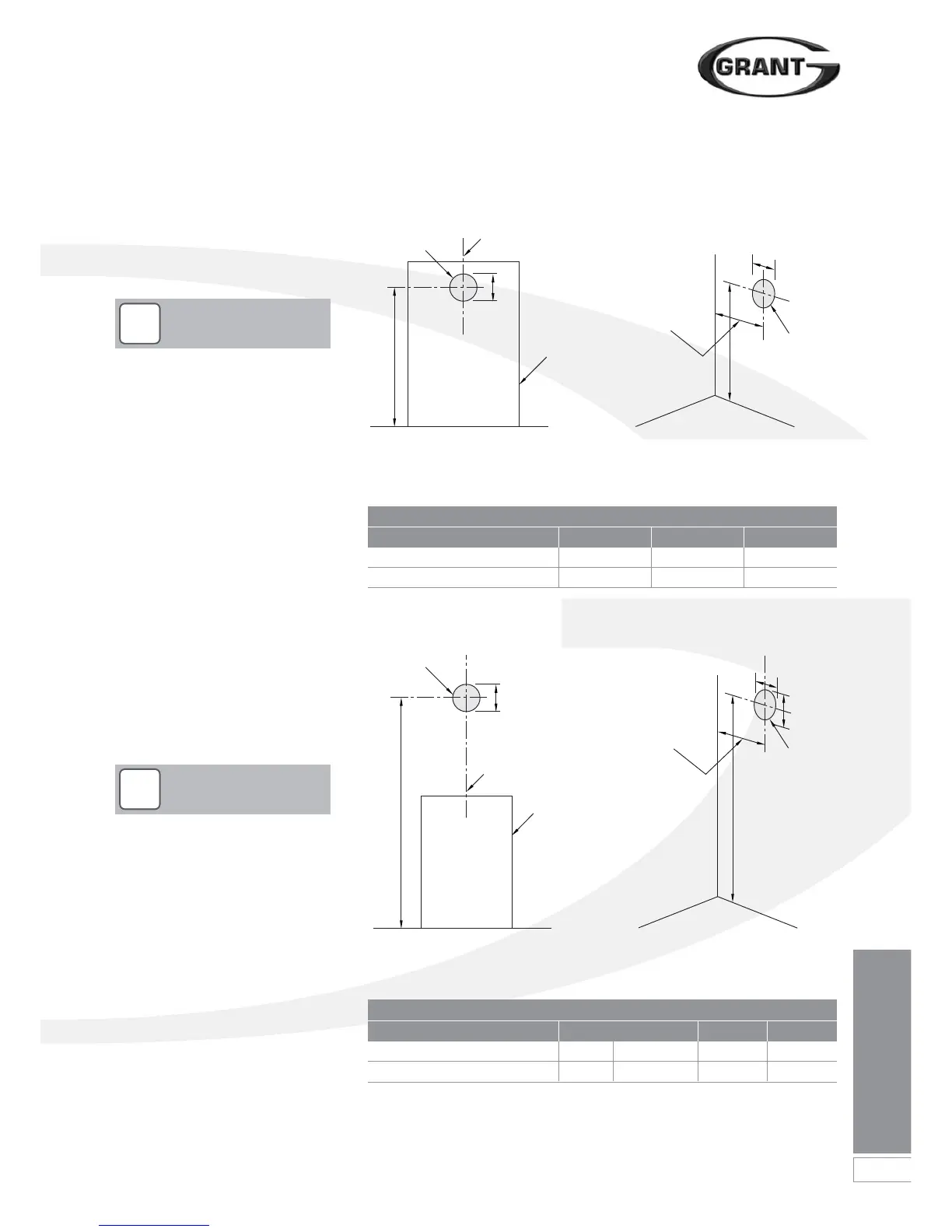
Figure 9-13: Flue hole dimensions and position for high level system (White)
Figure 9-12: Flue hole dimensions and position for low level systems (Yellow and
Green)
Model Dimension (mm)
A B C
Pro Combi 21e and 26e 768 127 115
Pro Combi 36e 780 162 105
Model Dimension (mm)
A B dia C
Pro Combi 21e and 26e 1215* 1715 - 2115 175 115
Pro Combi 36e 1280* 1700 - 2020 200 105
*Dimension A for Starter section and elbow/terminal only
Dimension B given in Figure 9-12
includes an extra 10mm over the size
of the terminal to provide clearance
for fitting.
9.5 Prepare the Wall
If the boiler is to be used with a low level
balanced flue (Yellow system) make the
hole in the wall for the flue as shown in
Figure 9-12.
A
B
A
B
C
Boiler centre line
Note: This dimension is
given with the boiler
pushed back against the
rear wall. Any clearances
must be added to it.
Outline of
boiler
Hole to be
drilled in wall
Hole to be
drilled in wall
Rear exit Side exit
Side wallRear wall
A
B
A
B
C
Boiler
centre line
Note: This dimension is
given with the boiler
pushed back against the
rear wall. Any clearances
must be added to it.
Standard kit with no extensions
Outline of
boiler
Hole to be
drilled in wall
Hole to be
drilled in wall
Rear exit Side exit
Side wallRear wall
 Loading...


