4.5 PIPEWORK MATERIALS
The Grant Vortex boiler is compatible with both copper and plastic
pipe. Where plastic pipe is used it must be of the oxygen barrier
type and be the correct class (to BS 7291-1) for the application
concerned.
On either sealed or open-vented systems; where plastic pipe is
used a minimum of ONE metre of copper pipe (or as per pipe
manufacturers instructions) MUST be connected between both
the boiler ow and return connections and the plastic pipe.
! NOTE !
Do not connect plastic pipe directly to the boiler.
Grant UK does not accept any responsibility for any damage,
however caused, to plastic piping or ttings.
SEALED SYSTEMS
If plastic pipe is to be used, the installer must check with the
plastic pipe manufacturer that the pipe to be used is suitable for
the temperature and pressures concerned.
Plastic pipe must be Class S to BS 7291-1.
! WARNING !
When plastic pipe is used, the system MUST incorporate
a low pressure switch to shut o power to the boiler if
the system pressure drops below 0.2 bar. A suitable low
pressure switch kit is available to purchase from Grant UK
(product code: MPCBS62).
UNDERFLOOR PIPEWORK
Plastic pipe may be used on underoor oor systems where the
plastic pipe is tted after the thermostatic mixing valve. Copper
tube must be used for at least the rst metre of ow and return
primary pipework between the boiler and the underoor mixing/
blending valves.
4.6 CONNECTIONS
4.6.1 FLOW, RETURN AND HOT WATER
CONNECTIONS
Refer to Section 5.
4.6.2 CONDENSATE CONNECTION
Grant Vortex Outdoor Combi boilers are supplied with a factory-
tted condensate trap to provide the required 75 mm water seal
in the condensate discharge pipe from the boiler.
Refer to Section 6 for details of the condensate disposal pipework.
4.6.3 DRAIN COCK
A drain cock is tted at the bottom on the front of the boiler to
allow the heating system to be drained.
There is also a drain cock tted at the bottom on the front of the
primary store.
4.7 PREPARATION FOR
INSTALLATION
1. Carefully remove the packaging from the boiler and remove it
from the transit pallet.
2. Remove the case top panel (four screws) and also the front
and rear panels as required.
3. The ue may exit the boiler from the left, right or rear of the
casing. Carefully press out the pre-cut section on the side
or rear casing panel to provide the opening in the required
position for the ue to pass through the casing.
Fit the cover panel (with the round ue exit hole) over the
chosen opening in the casing. Fit the circular rubber sealing
grommet provided into the circular hole in the cover panel
before tting the ue terminal section (or rst ue extension if
the ue is being extended using the green system).
4. Slacken the wing nuts holding the starter elbow and rotate
the elbow to the required direction for the ue to exit the
casing.
5. Push the end of the ue terminal section or ue extension
(with the red seal) from the outside of the boiler casing
through the sealing grommet in the casing panel. The
terminal section has been factory lubricated. Take care not to
dislodge or damage the red ue seal.
If using the low level ue option provided with the boiler:
6. Carefully insert the terminal into the starter elbow until the
bend of the terminal contacts the outer casing, then pull the
terminal forward approximately 25mm and rotate the bend so
that the outlet is horizontal.
Rear Exit - The ue must discharge away from the
building.
Side Exit - The ue should discharge towards the rear
of the casing to prevent ue gases re-entering the boiler
casing through the air inlet vents on the casing door.
The ue terminal must be tted horizontally to prevent
dripping from the end of the terminal.
If you are planning to extend the ue before terminating:
7. Carefully insert the rst extension/elbow piece into the starter
elbow and secure with a locking band.
8. Tighten the wing nuts holding the starter elbow and t the
stainless steel ue guard (if using low level ue option
provided with boiler) using the two screws provided.
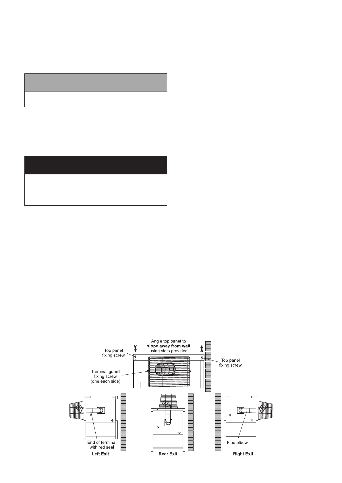
9. The top panel of the casing has been designed so that it
may be tted to create a slight slope away from the side
positioned against the wall. To tilt the top panel, loosen the
four top panel casing screws and push down on the side
furthest from the wall. Tighten the screws. See Figure 4-1.
Figure 4-1: Standard low level ue provided with Outdoor Module
Section 4: Installation Page 13
 Loading...


