Page 33Section 10: Commissioning
10 COMMISSIONING
To ensure safe and ecient operation, it is essential that a Grant
Vortex Pro Combi boiler is commissioned as detailed in the
following procedure.
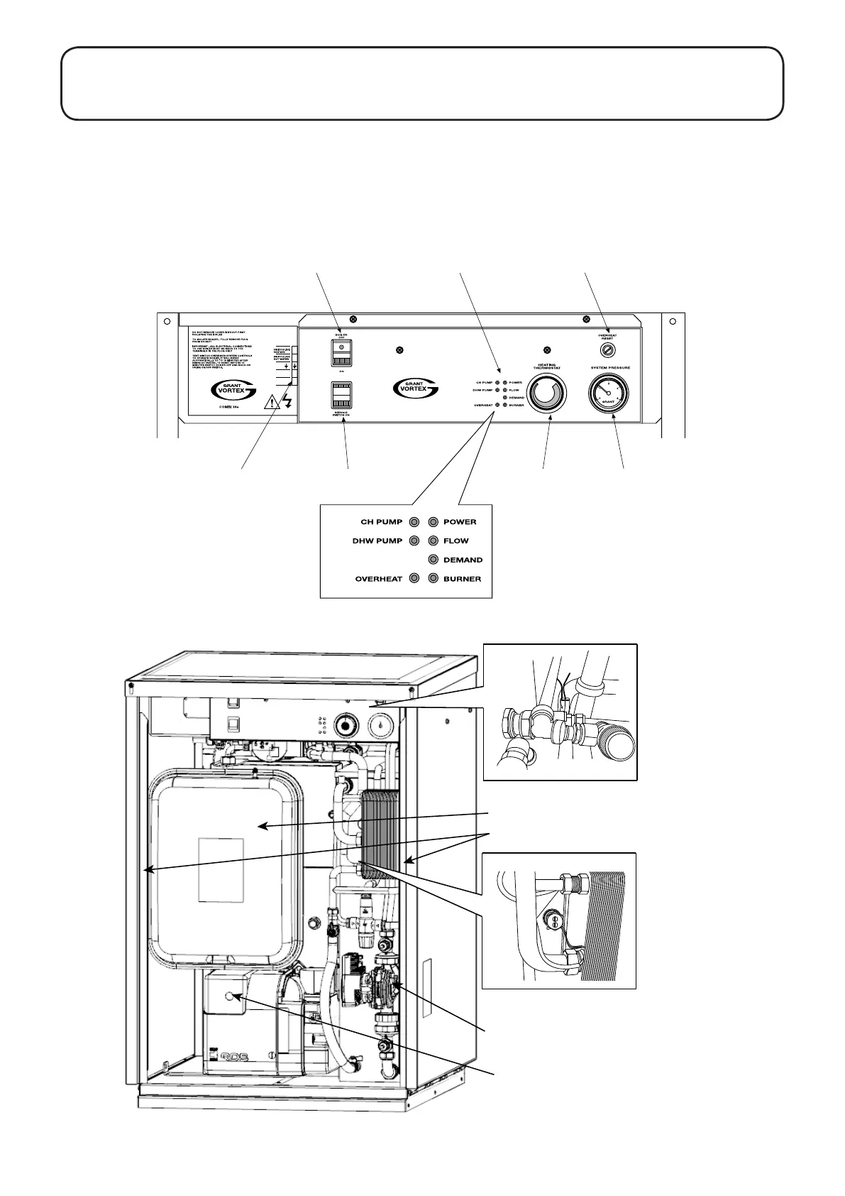
To access the controls, remove the front door from the boiler
casing (pull forward at the bottom and then lift o).
The controls are shown in Figure 10-1 and other components are
shown in Figure 10-2.
Electrical
connection socket
Service
switch
Boiler
thermostat
Pressure
gauge
Boiler On / Off switch Indicator lights
Overheat reset button
(under black cap)
IMPORTANT
CABLE TO PLUG MUST BE SECURED IN CABLE CLAMP BELOW PANEL
MAXIMUM CABLE LENGTH BETWEEN PLUG AND CLAMP 350mm
WARNING 230V ISOLATE MAINS POWER SUPPLY BEFORE REMOVING COVER
1
2
N
3
N
L
Figure 10-1: Vortex Pro External Combi boiler control panel
Figure 10-2: Position of boiler components - Vortex Pro Outdoor Combi
Hot water pump
Burner lock-out button
Casing door locating channels
Expansion vessel
Store sensor (white sleeve)
Flow sensor (black sleeve)
 Loading...


