Section 10: CommissioningPage 36
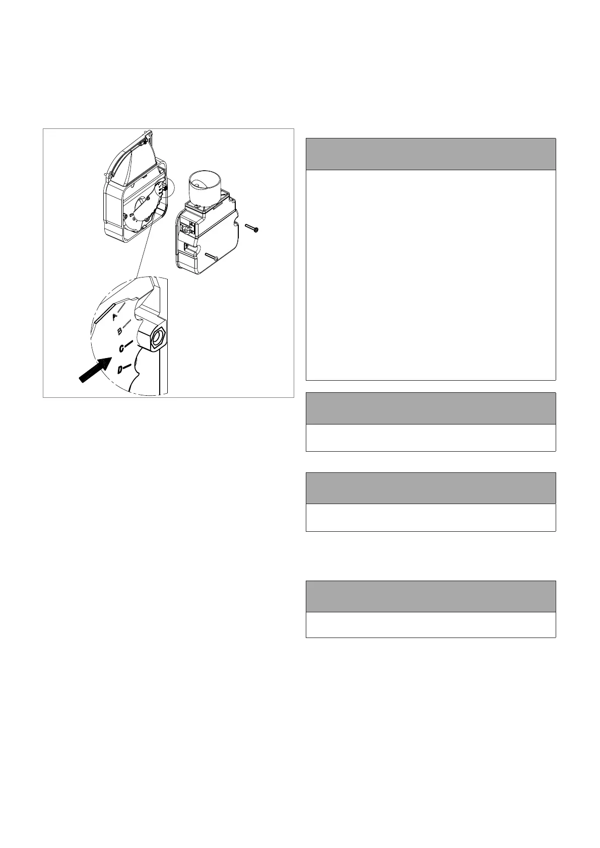
10.3 AIR ADJUSTER DISC:
COMBI 21 ONLY
The Riello RDB 2.2 BX burner tted to these boilers incorporates
a secondary air adjustment.
This is an air adjuster disc located on the fan housing (inside the
air inlet housing).
It is essential, for correct operation of the burner, that this internal
air adjuster disc is correctly set. Refer to Figure 10-6.
Figure 10-6: Air adjuster disc
To access the air adjuster disc:
1. Ensure the boiler is isolated from the electrical supply.
2. Remove the burner xing nut (located at the top of the
mounting ange) and withdraw the burner from the boiler.
3. Undo the two screws and remove the air inlet cover from the
side of the burner.
4. The air adjuster disc is mounted on the fan housing. Refer to
Figure 10-6.
5. Check that this disc is correctly set for the factory set output
of the boiler, i.e. with the correct cut-out mark located against
the moulded boss on the fan housing. Refer to Table 2-2 for
correct disc settings. If the disc is not correctly set it MUST
be re-positioned. Refer to step 6 below.
6. The air adjuster disc is re-positioned as follows:
• Remove the screw from the centre of the air adjuster
disc.
• Re-position the disc so that the correct cut-out is located
against the moulded boss on the fan housing.
• Replace the screw in the centre of the air shutter disc
and tighten.
7. Re-t the air inlet cover to the side of the burner and secure
in place using the two screws.
10.4 SWITCHING ON
1. Check that all system controls are calling for heat and turn
the boiler thermostat to maximum.
2. Switch on the electricity supply to the boiler.
3. Set the boiler On/O switch to ON. A neon on the switch
lights when it is in the ON position. Note that the neon lights
when the boiler is switched on, but does not necessarily
indicate the burner is ring.
Set both the Hot Water and Heating switches to ON. The
burner should then re. Open the vent screw on the vent
manifold to vent the supply while the oil pump is running
4. Fully open a hot tap and allow it to run for a few moments
to vent the internal primary circuit. The Hot Water pump will
operate and the burner should light within about 12 seconds.
If the burner does not light and the ‘Lock-out’ reset button
lights, wait for about 45 seconds then press the reset button
to restart the ignition process. This procedure may have to be
repeated during rst lighting.
5. Close the hot tap. The burner will continue to re to heat the
primary water in the boiler or primary store until the required
temperature is reached.
! NOTE !
Grant Vortex Combi boilers incorporate a “pump overrun”
feature, within the control circuit board, that operates as
follows:
• When reheating the Primary Hot Water store: the burner
will cut out when the boiler reaches 83°C (as detected by
the boiler “ow” thermistor).
• If there is a demand for Central Heating: the hot water
“store” pump will run on for 90 seconds before it stops and
the “central heating” pump then comes in.
• If there is no demand for Central Heating: the hot water
“store” pump will continue to run until the temperatures in
the Primary Hot Water store and the boiler have equalised.
The adjustable Boiler thermostat on the control panel
regulates the boiler temperature when in Heating mode
only. The recommended ow temperature setting is 70°C.
The Primary Hot Water store temperature is controlled via
the “store” thermistor and control circuit board. The control
thermostat has NO inuence on either the store temperature or
the hot water temperature at the tap.
! NOTE !
The hot water pump will continue to run for a short period
after the burner has stopped.
The boiler will now be operating in the central heating mode.
! NOTE !
The burner may not re immediately in the central heating
mode.
6. With the burner alight, check the fuel pressure. Refer to
Section 2.2 (burner settings).
7. Adjust the pressure if necessary - refer to Section 11.8
(Burner Components).
! NOTE !
It is important that the oil pressure is correctly set.
8. Operate the boiler until it reaches normal operating
temperature. Check oil supply/return pipe for leaks, rectifying
where necessary.
9. Check the operation of the boiler thermostat. Ensure that by
turning it anticlockwise it switches the burner o.
10. With the burner alight, re-check the fuel pressure and re-
adjust if necessary. Turn the boiler o, remove the pressure
gauge and replace the plug in the pump.
11. Ensure that there are no oil leaks, replace the burner cover.
 Loading...


