Page 35Section 10: Commissioning
! NOTE !
Do not overtighten the xing screw as this may damage
the electrode insulator.
±0.5
A
±0.3
B
C
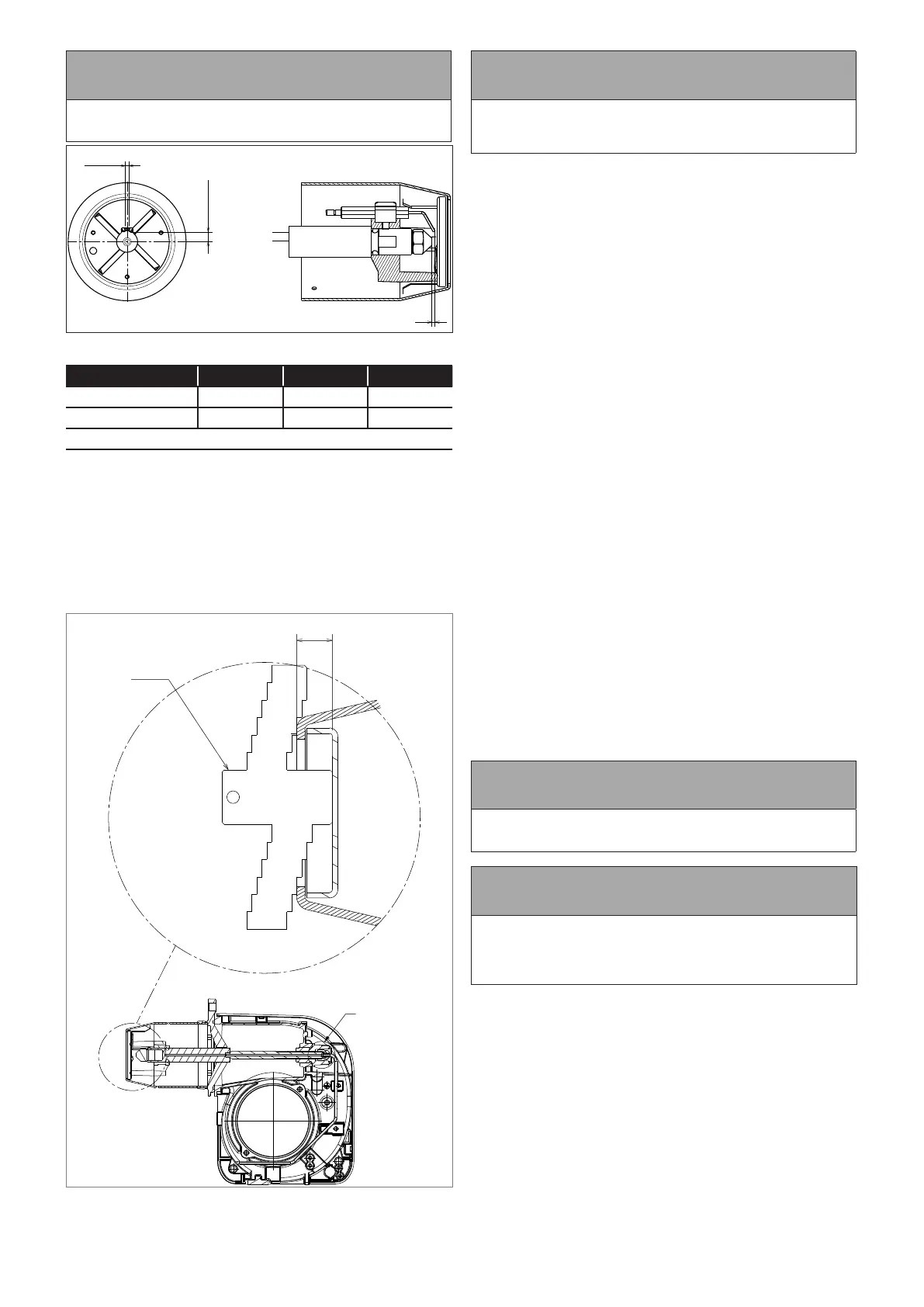
Figure 10-4: Ignition electrode settings
Model A B C
Combi 21 and 26 7 2.5 2.5 - 3
Combi 36 4.5 3 2 - 2.5
Note: all dimensions given in mm
6. Check/adjust electrode setting. Refer to Figure 10-4.
7. Re-t the burner head. Refer to Figure 10-3.
• Locate the head xing screws (1) in the countersunk
slots in the burner collar.
• Check that the small oil drip hole (on the head) is
pointing downwards.
• Tighten the three screws (1) to secure the head (2) in
position on the burner.
8. Adjust the diuser position. Refer to Figure 10-5.
Figure 10-5: Riello RDB 2.2 BX diuser position and gauge plate
! NOTE !
The distance between the end of the burner head and the
front face of the diuser (D) MUST be correctly set for the
burner to operate correctly.
• Refer to Table 2-2 for the required distance (head
setting) for the boiler output required.
• Check the distance D using the gauge plate supplied
with the boiler.
• To use the gauge plate:
- Position the gauge on the burner head as shown in
Figure 10-5.
- Locate the gauge with the correct steps (i.e. the two
marked with the required distance D) resting on the
edge of the burner head.
- Check the gauge plate is at 90° to the end of the
burner head and is positioned at the full diameter of
the head.
- If the distance D is correct, the tongue of the gauge
plate should just make contact with the diuser,
with BOTH steps still in contact with the edge of the
burner head.
- If the steps are not in contact with the edge of the
burner head, when the tongue of the gauge is
touching the diuser, the diuser must be ‘opened’
(see below).
- If the tongue does not reach the diuser, when the
steps are in contact with the edge of the burner
head, the diuser must be ‘closed’ (see below).
• To adjust the diuser position:
- If necessary, adjust distance D using the black
adjustment knob located around the oil supply pipe
on the front of the burner. Refer to item A (Figure
10-5). Re-check distance D using the gauge plate,
as described above.
- For easier access to the adjustment knob, pull the
photocell out from the burner housing.
- To increase distance D (to open the diuser): rotate
the knob clockwise - indicated as ‘+’ on the knob.
- To decrease distance D (to close the diuser):
rotate the knob anti-clockwise - indicated as ‘-’ on
the knob.
! NOTE !
One full rotation of the adjustment knob is approximately
1mm of diuser movement.
! NOTE !
It is essential that the nal position of the diuser is
checked, using the gauge plate provided with the boiler
and the diuser adjusted as necessary to achieve the
required distance D.
9. For Combi 21 models only:
Check the burner air adjuster disc is correctly set. Refer to
Section 10.3.
 Loading...


