Section 8: ElectricalPage 24
8.3 CONNECTING THE CONTROLS -
HEATING ONLY
To control the central heating on / o periods only (and NOT the
domestic hot water), it is recommended to use a single channel
timer and room thermostat.
These should be sited at a suitable and convenient location within
the property.
The switched live from these central heating controls must be
connected to Terminal L1 on the boiler electrical isolation plug.
Refer to Figure 8-2 for connection details.
When using the boiler in this way, i.e. controlling the heating
operation of the boiler only, a link must be tted between
terminals L2 and L3 in the isolation plug. This will enable the
boiler to operate to supply hot water on demand at all times.
CONNECTION OF AN EXTERNAL REMOTE TIMER
AND ROOM THERMOSTAT
! WARNING !
Any remote timer must be of a single channel 230V type
with voltage free output contacts. Refer to Figure 8-2 for
connection details.
Connect the switched live output from the programmer/room
thermostat to terminal L1 of the boiler isolation plug. Fit a link
between terminals L2 and L3 in the isolation plug. Refer to Figure
8-2.
Connect the mains supply to the boiler isolation plug as follows
(refer to Figure 8-2):
• Permanent live to terminal L3.
• Neutral to terminal N.
• Earth to earth terminal.
Re-connect the electrical supply and check the operation of the
timer and room thermostat.
Refer to the Fitting & User instructions provided for with the timer
for operating and setting.
Leave the Timer and Thermostat Fitting & User instructions with
the user after installation.
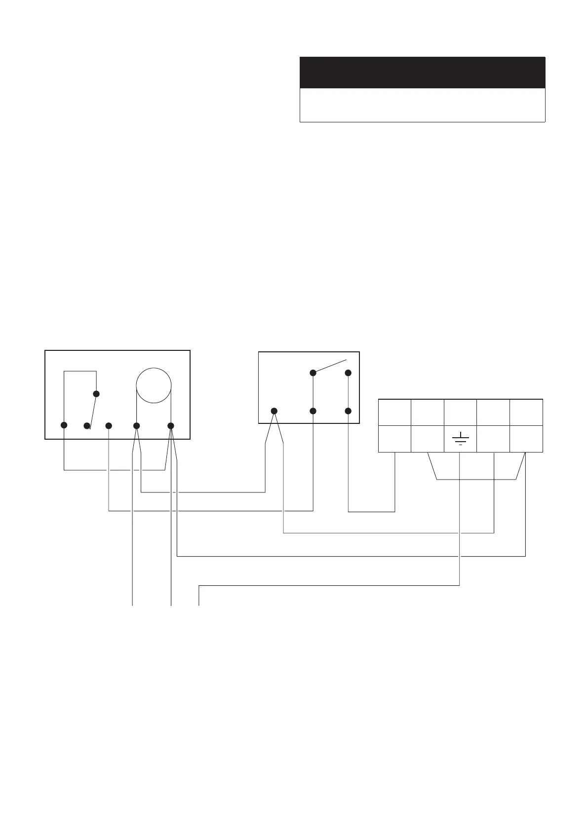
Room thermostat
e.g. Danfoss Randall RMT 230
Remote mounted time switch
e.g. Danfoss Randall TS 715
Boiler isolation plug
CH HW E N L
L1 L2
N
L3
4 1 2
1 2 4 N L
EN L
230V 5A Fused
main supply
Figure 8-2: Connections for remote timer and room thermostat
 Loading...


