Section 8: Electrical Page 23
BL
1A DR
DR2A
BL
5B
4B
On/O
Switch
C/W Neon
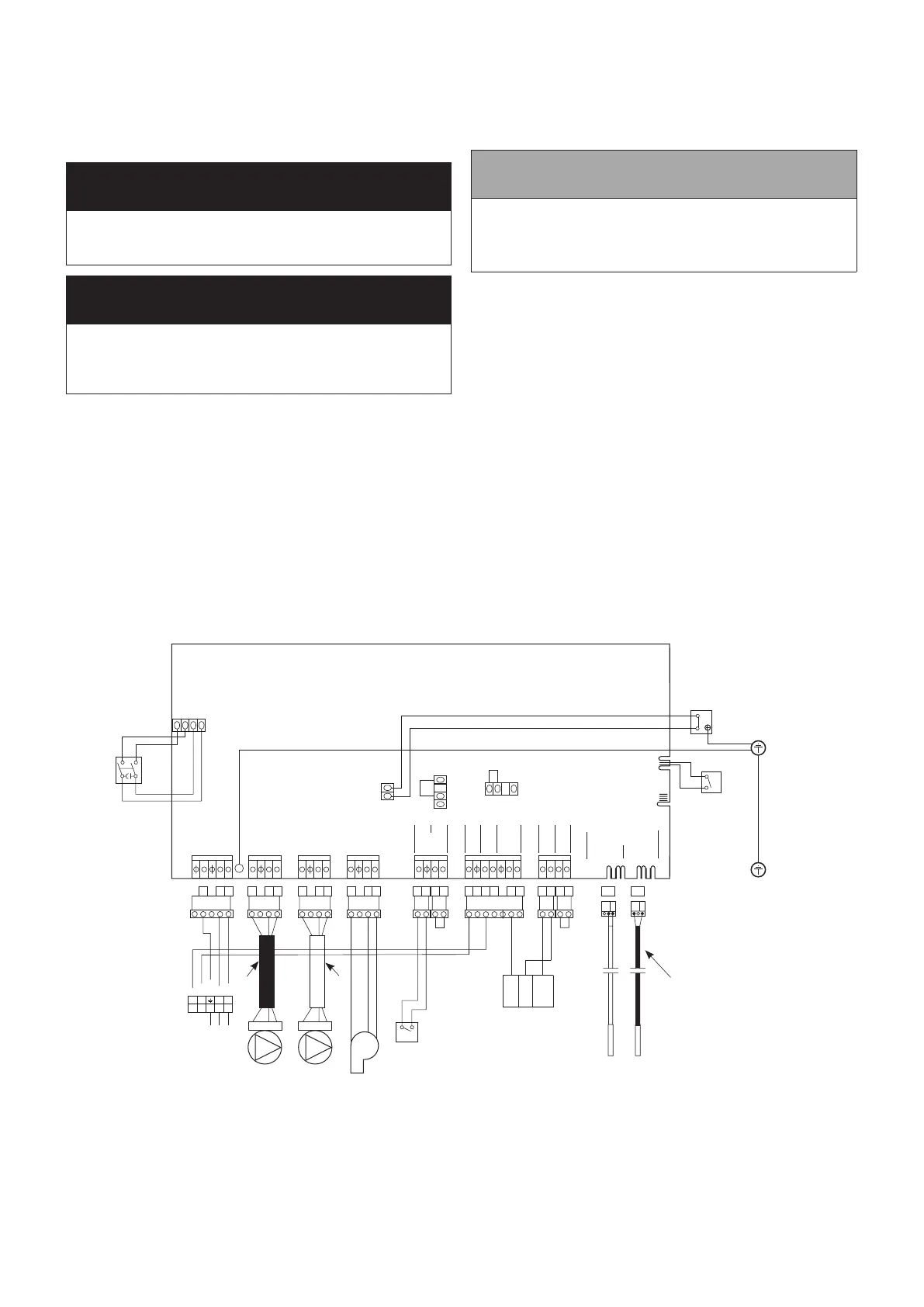
Printed Circuit Board
Mains
E N L
321
CH Pump
E N L
654
DHW Pump
E N L
987
Burner
E N L
10 11 12
Flow
Switch
13 14 15 16
DHW
Timed on
CH
Timed on
Timer Neutral
Timer Live
17 18 19 20 21 22 23 24 25 26
27 28
EXT Frost Stat (from)
EXT Frost Stat (to)
Room Stat (from)
Thermistors
Store Flow
ORBR
No
Flow
Switch
Store
Thermistor
Flow
Thermistor
Black shroud
indicates ow
thermistor
Earth connection
boiler top bracket
Burner
DHW
Pump
CH
Pump
E N L
E N L
E N L
Switched live CH
Switched live DHW
Boiler isolation
plug
Y
OR
G/Y
BL
RD
Black
Cable
White
Cable
Timer
RD
GR
GR
G/Y
Limit
Thermostat
2
C
G/Y
G/Y
Earth post
Control Panel Chasis
Service
Switch
BR
BR
Colour code:
BR - Brown
BL - Blue
RD - Red
G/Y - Green/Yellow
BLK - Black
OR - Orange
Y - Yellow
GR - Grey
N L ON
N L 3
Frost thermostat
(if required)
e.g. Danfoss Randall
RET230F
Figure 8-1: Boiler Wiring Diagram
4. Make the remaining required connections to the control
panel, as detailed in this section.
5. Replace the cover on the plug, ret the two screws and
ensure it is securely tted. Measure a maximum of 350mm
of cable between the plug and the cable clamp below the
control panel and tighten the cable clamp to secure the
cable.
! WARNING !
Check that the cable is securely clamped and that the
cable length between the clamp and the plug is no more
than 350mm.
! WARNING !
After completing electrical connections and before
reconnecting the electrical supply to the boiler, replace the
wiring cover on the plug and secure it using the screws
provided.
6. Re-t the isolation plug into the socket in the control panel.
7. Replace the top casing panel and four retaining screws
following the procedure outlined in Section 4.7 and replace
the casing door.
8. Re-connect the electrical supply and check operation of
heating system controls (programmer, room thermostats,
etc.).
9. Refer to Instructions provided with the programmer for
operation and setting.
10. Leave the Programmer and Thermostat Instructions with the
user after installation for their future reference.
BURNER LEAD PLUG/SOCKET CONNECTOR
On all models, the electrical cable between the boiler control
panel and burner is now tted with an in-line 3-way plug
and socket connector. This enables the burner to be easily
disconnected from the boiler control panel for ease of removal for
servicing.
! NOTE !
A Service switch is tted to the control panel to allow the
Service Engineer to test-re the boiler.
When set to ‘ON’ the switch temporarily by-passes the
external control system to operate the boiler.
This is a ‘momentary’ or non-latching switch that cannot be left
set to ON. The boiler will automatically revert to normal operation
when 15 minutes have elapsed since it was last operated.
If required, this 15 minute override period can be stopped by
switching the boiler On / O switch OFF and then back to ON.
The boiler will then operate as normal under control of the
external heating/hot water controls (timer, room thermostat or
programmer).
 Loading...


