Section 7: Sealed SystemsPage 20
7.1.2 PRESSURE GAUGE
The pressure gauge is factory tted in the boiler control panel. It
has an operating range of 0 to 4 bar. Refer to Section 1.4.
7.1.3 PRESSURE RELIEF (SAFETY) VALVE
The pressure relief (safety) valve is factory tted to the ow
pipework on the top of the boiler.
A discharge pipe should be connected to the outlet of the pressure
relief (safety) valve. This discharge pipe must terminate in a
position that will allow the discharge to be seen, but cannot cause
injury to persons or damage to property. Refer to Figure 5-1 for
the position of the PRV on all models.
7.1.4 FILLING LOOP
In order to ll or top up the heating system, a factory tted
lling loop is located at the front of the boiler, to the right of the
expansion vessel.
Refer to Section 7.2 for details on how to ll and vent the system.
7.1.5 HEATING SYSTEM
The maximum ‘setpoint’ temperature for the central heating water
is 75°C. Refer to Section 1.1.
An air vent should be tted in the ow and return pipes of the
highest point of the system.
If thermostatic radiator valves are tted to all radiators, a system
by-pass must be tted. The by-pass must be an automatic type.
All ttings used in the system must be able to withstand pressures
up to 3 bar. Radiator valves must comply with the requirements of
BS 2767.
One or more drain taps (to BS 2879) must be used to allow the
system to be completely drained.
7.1 SEALED SYSTEM
REQUIREMENTS
All Grant Vortex Pro Combi boilers must be used as part of a
sealed system complying with the requirements of BS EN 12828,
BS EN 12831 and BS EN 14336.
The maximum temperature of the central heating water is 75°C.
The boiler is supplied factory tted with the following items:
• 24 litre diaphragm expansion vessel complying with BS EN
13831
• Pressure gauge
• Pressure relief (safety) valve
• Approved lling loop
7.1.1 EXPANSION VESSEL
On all models the expansion vessel is factory tted on the front of
the boiler, inside the casing.
It is connected to the boiler via a exible hose to allow the vessel
to be removed from the boiler to access the front cleaning door
without disconnecting it. Take care to ensure that the exible hose
is not twisted or kinked.
Refer to Section 4.9 for further installation details.
! NOTE !
Ensure that the expansion vessel is of sucient size for
the system volume.
Refer to BS 7074-1 or the Domestic Heating Design Guide
to check the vessel size required.
7 SEALED SYSTEMS
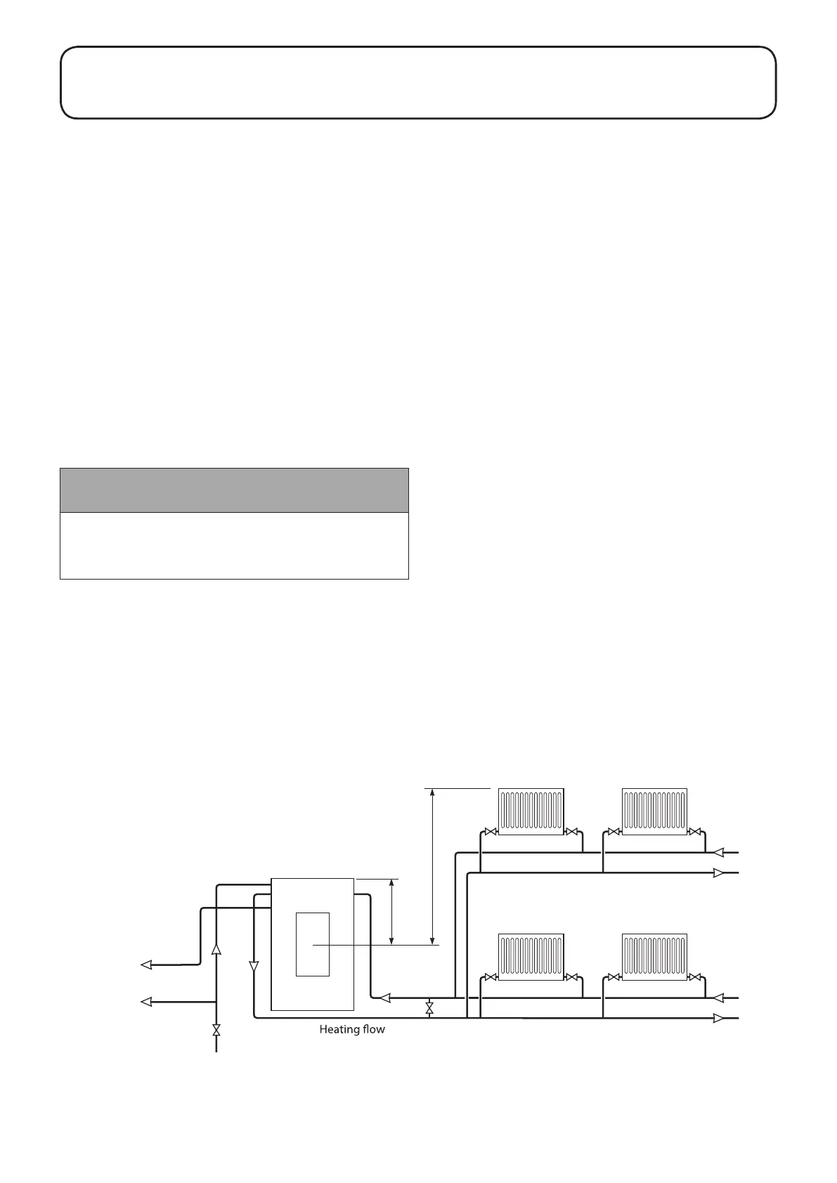
Figure 7-1: Sealed system
If thermostatic radiator valves
are fitted, the system must
incorporate an adequate by-pass.
Static head of system
350mm
Heating
return
By-pass if required
(automatic type)
Expansion
vessel
Boiler
Stop valve
Water mains
Domestic
cold water
Domestic
hot water
 Loading...


