Page 16
ALL MODELS
A 15 mm discharge pipe must be connected to the safety valve
outlet connection. The pipework between the safety valve and the
boiler must be unrestricted, that is, no valves. The discharge pipe
should be run to the outside of the building and terminate so that it
cannot cause injury to persons or property.
A drain tap is provided at the bottom on the front of the boiler (and
also on the hot water store on the Vortex Pro Combi).
5.2 MAKING THE WATER
CONNECTIONS
Flow and return pipework can be routed to either side of the
boiler (dependant on the ue system used and where it exits the
boiler) or can be routed through the base of the enclosure, from
the push-t elbows (supplied) on the ow and return connections.
Refer to Figure 5-1 for ow and return pipework positions.
Holes are provided in the rear of the casing side panels to allow
the condensate pipe to be run through the back of the boiler. It will
be necessary to remove the back panel from the boiler casing to
t this pipework, and to ret the panel before placing the boiler in
its nal position. Refer to Figures 6-2 & 6-3.
If access will be restricted, make any connections to the boiler
before placing it in its nal position.
5.3 DOMESTIC HOT WATER
SYSTEM
To maintain a longer and more consistent hot water temperature,
a ow restrictor is factory tted to the Vortex Pro Combi 21 to limit
the ow rate to approximately 12 litres/minute, and to the Vortex
Pro Combi 26 to limit the ow rate to approximately 15 litres/
minute.
The ow restrictor is located in the outlet side of the cold water
inlet isolating valve.
A ow restrictor is not tted to the Vortex Pro Combi 36.
The incoming mains water pressure should be between 1 and 8
bar to ensure ecient operation.
! NOTE !
If the pressure is above 8 bar a pressure reducing valve
must be tted.
The boiler may still operate down to a pressure of 1.0 bar but with
a reduced ow rate. The minimum ow rate needed for the ow
switch to operate is 3 litres/minute.
To ensure economic use, the pipe runs between the boiler and
hot taps should be as short as possible and in 15 mm copper pipe
or 22 mm for the Vortex Pro Combi 36 only. Where possible the
pipework should be insulated to reduce heat loss.
All taps and mixing valves used in the domestic hot water system
must be suitable for operating at a mains pressure of up to 8 bar.
If required, a shower may be tted in the domestic hot water
system. It is recommended that thermostatically controlled
shower valves are used to protect against a ow of water at too
high a temperature. If a xed head type shower is used, no anti-
syphonage devices are required. If a loose or exible head type
shower is used, it must be arranged so that the head cannot fall
closer than 25 mm above the top of the bath, thereby preventing
immersion in the bath water. If this is not practicable, an anti-
syphonage device must be tted at the point of the exible hose
connection.
The supply of hot and cold mains water direct to a bidet is allowed
(subject to local Water Undertaking requirements) provided
that the bidet is of the overrim ushing type. The outlets should
be shrouded and unable to have a temporary hand held spray
attached. Arrangements for antisyphonage are not necessary.
Before the mains water supply pipe is connected to the boiler, it
should be thoroughly ushed out to avoid the danger of dirt or
foreign matter entering the boiler.
The mains water connection to the boiler must be the rst
connection from the mains supply.
5.4 TO USE THE WATER
HARDNESS KIT
! NOTE !
A water hardness test kit is supplied with the boiler. Should
the total hardness of the water supply exceed 125 ppm,
an in-line scale inhibitor should be tted in the cold water
supply to the boiler.
Consult the local Water Undertaking if in doubt.
Do not immerse the test strip in running water and avoid
contact.
1. Fill a clean container with a sample of water from the mains
cold water supply to the boiler.
2. Immerse the test strip in the water for approximately one
second, ensuring that all the test zones are fully wetted.
3. Shake o the surplus water and wait for one minute.
4. Assess the colouration of the test zones using the following
chart.
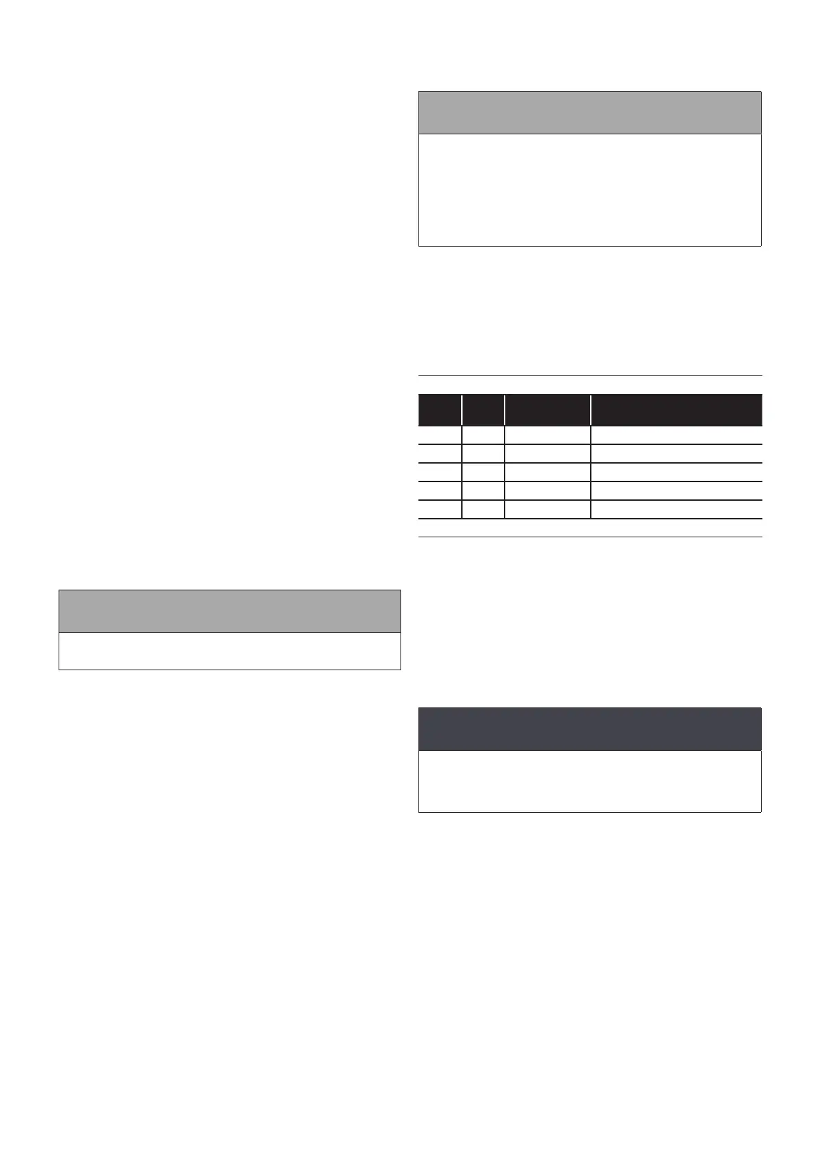
Table 5-1: Key to water hardness
Green
areas
Violet
areas
Hardness Total hardness mg/l (ppm)
4 0 Very soft <50 mg/l calcium carbonate
3 1 Soft <70 mg/l calcium carbonate
2 2 Medium <125 mg/l calcium carbonate
1 3 Hard <250 mg/l calcium carbonate
0 4 Very hard <370 mg/l calcium carbonate
Note: 1mg/l = 1 ppm (part per million)
If the hardness reading is found to be in the medium to very hard
range (the shaded area), it is essential that some form of water
conditioner or softener is tted to reduce scale formation within
the combination boiler. Failure to do so may invalidate both the
manufacturers guarantee and any extended guarantee covering
the appliance.
The water conditioner or softener should be tted to the cold
water supply serving the appliance and in accordance with the
manufacturer’s instructions. Grant UK cannot be held responsible
for any damage or misuse caused by the tting of any water
conditioning device.
! CAUTION !
Please protect the domestic hot water system from
harmful eects of scale. Problems caused by the build-
up of limescale are not covered under the terms of the
guarantee.
Section 5: Pipe Connections
 Loading...


