Super Free Match
Service Manual
INSTALLATION
108
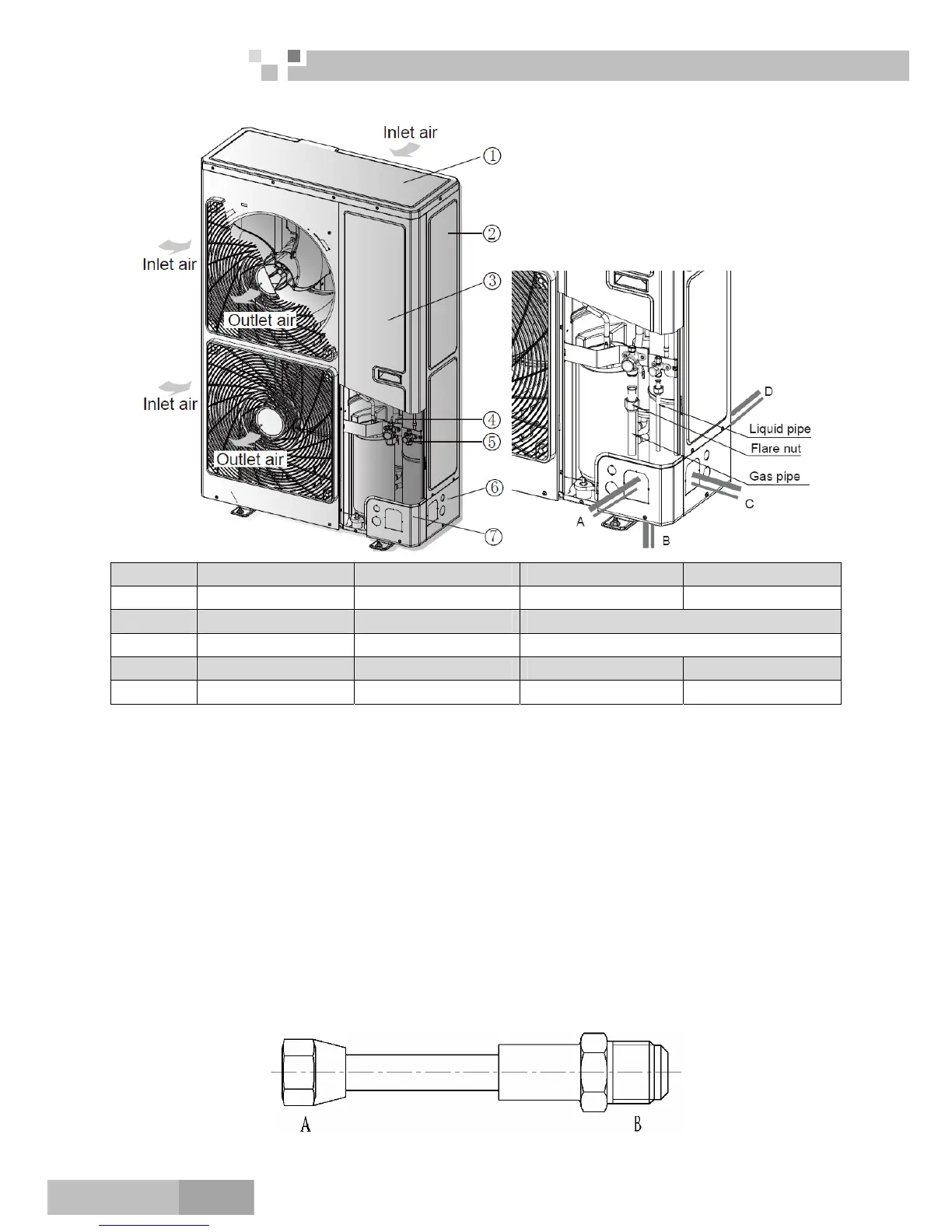
6.6 Connection of Outdoor Unit Refrigerant Pipe
NO. ① ② ③ ④
Name Coping plate Rear side plate Front side plate Gas side stop valve
NO. ⑤ ⑥ ⑦
Name Liquid side stop valve Right connection board Front connection board
NO. A B C D
Name Front connection Bottom connection Side connection Rear connection
1) Unscrew the coping plate, front side plate, right connection board and front connection board.
2) The refrigerant pipes can be installed in four directions, please choose the proper direction.
3) Knock the holes in the plate of the chosen direction with the drill and hammer.
4) Connect the pipes to the stop valves.
5) Bend the pipes to go through the knockout holes.
6) Cover the through-holes with sealing materials to prevent the water, dust or small animals going into the
outdoor unit.
6.7 Installation of Piping Adapter
If the piping connection size of BU module does not match with that of the outdoor unit and indoor units, it
should prevail with the piping connection size of the outdoor unit and indoor units.Install the optional piping
adapters to the BU module, so that the piping connection size of BU module can match with that of the outdoor
unit and indoor units.
6.8.1 FXA2A-K and FXA3A-K
1) Piping adapter(Optional)
 Loading...