EasyManua.ls Logo

Gree GC201306 -1 User Manual

Gree GC201306 -1
216 pages
To Next Page IconTo Next Page
To Previous Page IconTo Previous Page
Page #131 background imageLoading...
Page #131 background image
Super Free Match
Service Manual
MAINTENANCE
N
127
MAINTENANCE
1 Testing Board Introduction
The testing board is in the front of electrical box and can be observed well. It has several following
advantages:
Automatically detect indoor unit numbers
Automatically assign indoor unit addresses
Automatically display real running function and error code
Option settings to suit the demand of the customer
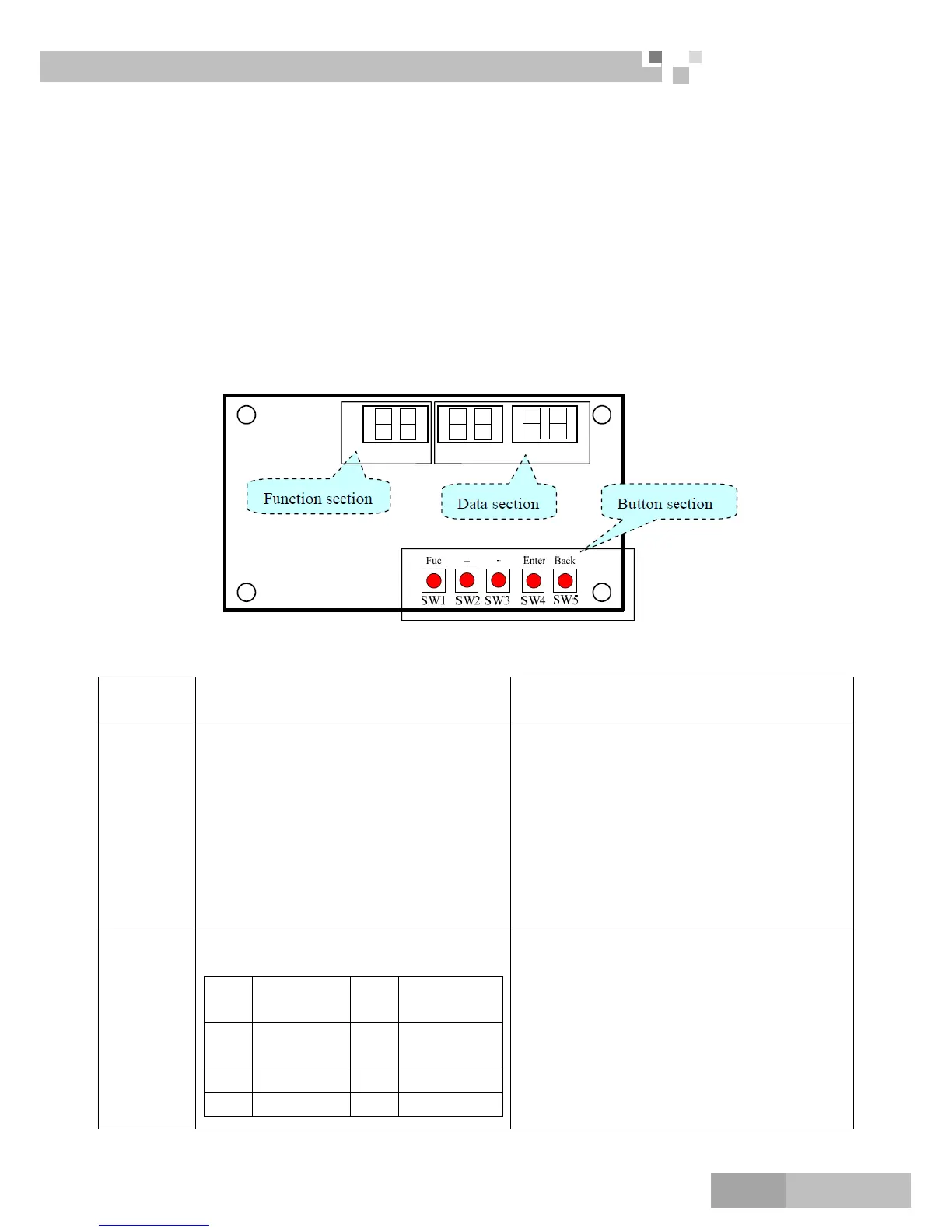
1.1 Compose of Testing Board
The testing board is composed of the function section, data section and button section.
1.2 Instruction of Function and Data Section
Running
state
The display of function section The display of data section
Stop
The section will display the numbers of the
indoor units which have established
communication with the outdoor unit. For
example, if there are seven established
indoor units, the section will display “7”.
It will display the address of the indoor
units by turns. For example, the “1b” is
represented of the indoor unit 1B.BU
module:1/2/3Indoor unit: A/B/C
If the function section displays the numbers of
the indoor units, the data section will display the
outside temperature. For example, the “35” is
represented of 35.
If the function section displays the address of
the indoor unitthe data section will display the
capacity of the indoor unit, for example, the
“35” is represented of 3500W.
Normal
The code of running state:
Code
Running
state
Code Running state
UE
Pressure
equalization
UH Heating
UP Pump down F7 Oil returning
UC Cooling H1 Defrosting
It displays the target gear of the compressor. If
the gear is zero, it will display “0”. For example, the
gear is the fifteenth; it will display “15”. The range
of the gear is from 0 to 60.

Table of Contents

Question and Answer IconNeed help?

Do you have a question about the Gree GC201306 -1 and is the answer not in the manual?

Gree GC201306 -1 Specifications

General IconGeneral
BrandGree
ModelGC201306 -1
CategoryAir Conditioner
LanguageEnglish

Summary

Product Overview and Specifications

Models List

Lists and details specifications for outdoor, BU, and indoor units.

Nomenclature Guide

Explains the coding system for outdoor, BU, and indoor unit model names.

Technical Product Data

Provides detailed technical specifications for outdoor, indoor, and BU modules.

Working Temperature Ranges

Specifies the operating temperature ranges for indoor and outdoor units.

Piping Diagram Schematic

Illustrates the refrigerant piping schematic for the system.

System Control and Operation

Operation Flowcharts and Logic

Visualizes the operational sequence and main logic of the unit.

Protection Functions and Error Codes

Lists and explains various protection functions and error codes.

Remote Controller Operations

Details operation of wired and wireless remote controllers, including modes and features.

Installation Procedures

Installation Precautions and Flowchart

Safety precautions, general installation rules, and overall installation flowchart.

Outdoor Unit Installation

Step-by-step guide for installing the outdoor unit, including precautions.

Indoor Unit Installation

Detailed instructions for installing various indoor unit types.

BU Module Installation

Procedures for selecting location and installing BU modules.

Piping and Wiring Procedures

Covers pipe dimensions, connections, leak tests, vacuuming, and wiring.

Drainage Pipeline Installation

Guidelines for installing condensate and drain pipes, including precautions.

Maintenance and Troubleshooting

Testing Board and Process Control

Introduction to the testing board, its components, and process control settings.

Troubleshooting Guide

Detailed troubleshooting flowcharts and problem handling for common issues.

Power Distribution and Wiring Diagrams

Diagrams showing power distribution and electrical wiring for system components.

Temperature Sensor Data

Tables of resistance and voltage values for common temperature sensors.

Disassembly and Assembly Procedures

Step-by-step guides for disassembling and assembling main parts.

Exploded Views and Part Lists

Detailed exploded views and part lists for system components.

Related product manuals