APEX™ Exciter Incorporating FLO™ Technology
Theory of Operation APEX Exciter Digital Assembly Overview
Page: 4-4 888-2604-001 03/08/07
WARNING: Disconnect primary power prior to servicing.
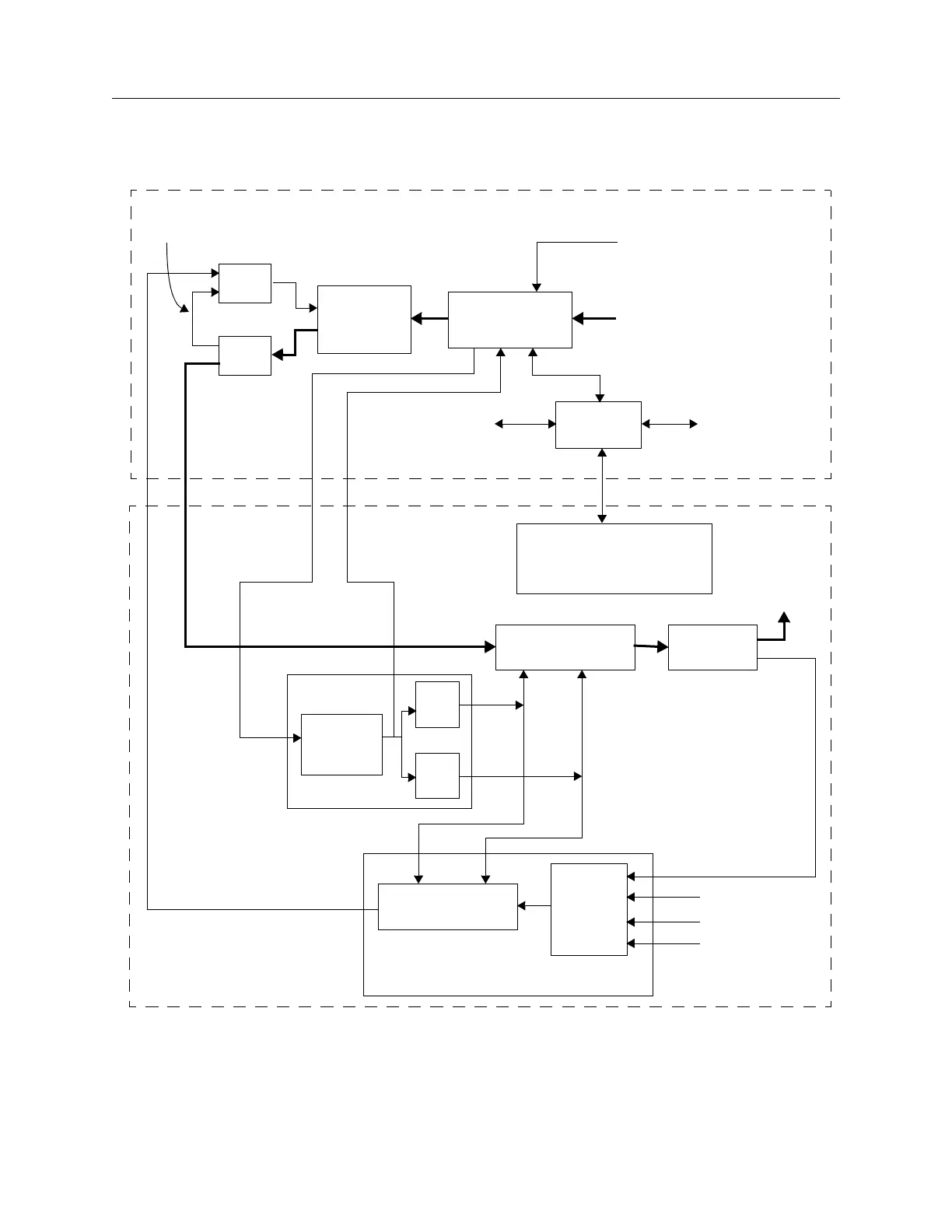
Figure 4-2 APEX Exciter - Signal Flow Block Diagram
RF Output
Amplifier
Up Converter
(double converted)
Multiple
Input
Down Converter
(double converted)
RF
Switch
Down Converter Board
PLL Board
1st
L.O.
2nd
L.O.
10 MHz
Reference
Exciter Sample Input
PA Sample Input
HPF Sample Input
Exciter RF
Output
DAC
ADC
Adaptive
Precorrector
Board
FPGA Modulator
Board
ASI Transport
Stream Input
Top (Analog) Side
UDC Interface Board
(Controls Up Converter, PLL
and Down Converter Boards)
Controller
Board
Control Signals
To and From all
Digital Boards
Control Signals
To and From
Front Panel
Display Board
Bottom (Digital) Side
Analog
Loopback
External
1PPS Input
Oscillator
10 MHz10 kHz

 Loading...
