APEX™ Exciter Incorporating FLO™ Technology
Details of the System Setup Screens Navigating the LCD Display Screens
2604s300.fm
03/08/07 888-2604-001 Page: 3-51
WARNING: Disconnect primary power prior to servicing.
3.6.7.4 FPGA Configure 4/5
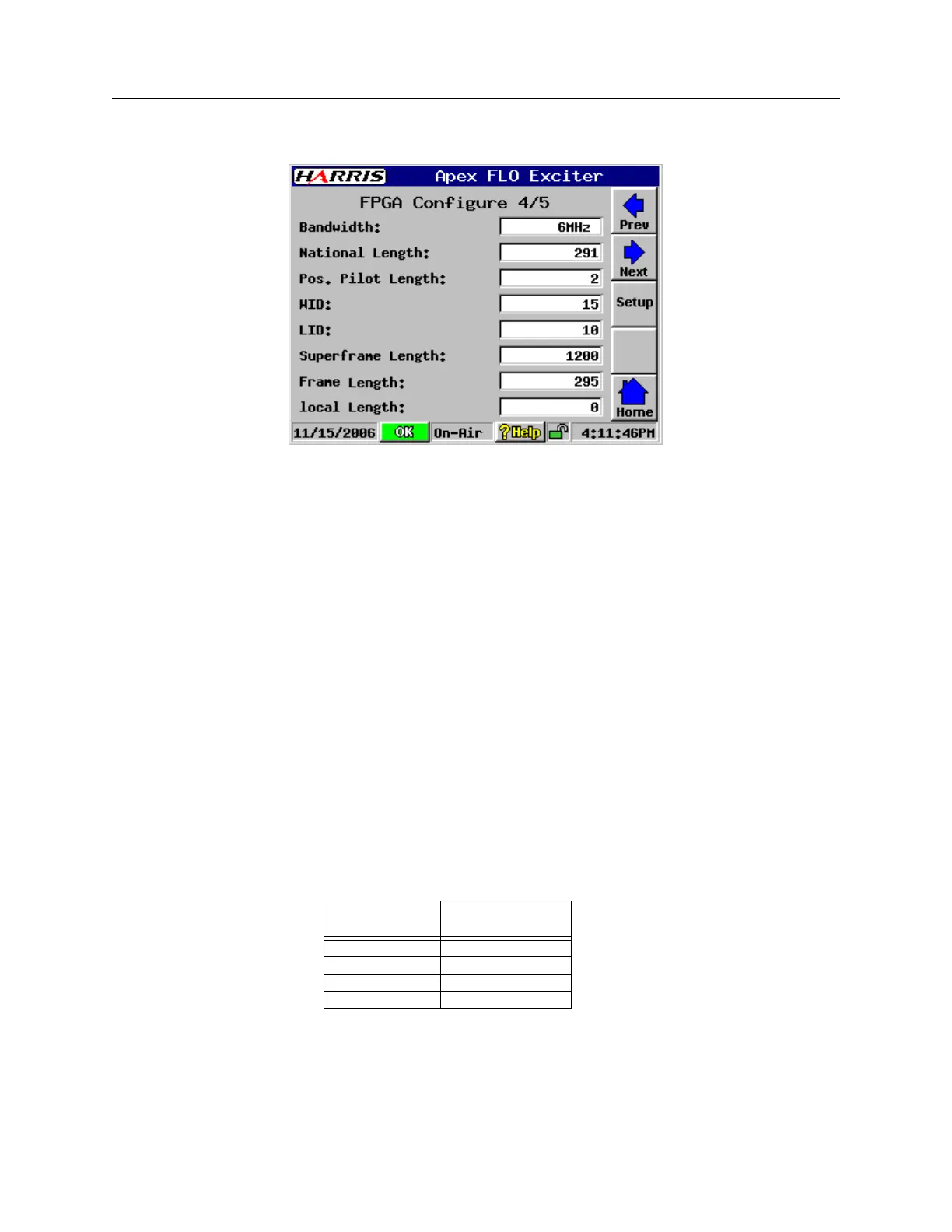
FPGASetup4.bmp
Figure 3-43 FPGA Configure 4/5
FPGA Configure 4/5 consists of registers whose values are written immediately to the
FPGA when changed through the GUI.
FPGA re-initialization shall occur automatically after any FPGA Configure 4/5 register is
changed.
The parameters of the FPGA Configure 4/5 screen are as follows.
• Bandwidth: 5MHz / 6MHz / 7MHz / 8MHz
• National Length: Unsigned Decimal, range dependent on bandwidth:
0-245 5MHz, 0-295 6MHz, 0-345 7MHz, 0-395 8MHz
• Pos. Pilot Length: 2 / 6 / 10 / 14 – not bandwidth dependent
• WID: Unsigned Decimal, range 0-15
• LID: Unsigned Decimal, range 0-15
• Superframe Length: Unsigned Decimal integer, displayed only, not user config-
urable
Superframe Length is written to the FPGA register and displayed on the screen. It is
based on the Bandwidth setting as shown in the following Table:
• Frame Length: Unsigned Decimal integer, displayed only, not user configurable –
see below)
Frame Length shall be calculated, written to the FPGA register, and displayed based
on the following formula:
Bandwidth
Superframe
Length
5 MHz 1000
6 MHz 1200
7 MHz 1400
8 MHz 1600

 Loading...
